Home › BRAKE › BRAKE CONTROL › ELECTRONICALLY CONTROLLED BRAKE SYSTEM

DTC    C1247/47    Stroke Sensor Malfunction

DTC    C1392/48    Stroke Sensor Zero Point Calibration Undone

for Preparation Click here


DESCRIPTION

The stroke sensor inputs the pedal stroke into the skid control ECU.

DTC No.
INF Code
DTC Detection Condition
Trouble Area
C1247/47
171
Sensor power source voltage (VCSK) is 3.6 V or less or 4.95 V or more for at least 1.2 sec.
  1. Brake pedal stroke sensor
  2. Skid control ECU
  3. Harness and connector
C1247/47
172
Ratio of sensor output voltage 1 (SKS1) to sensor power source voltage (VCSK) is less than 3% or 97% or more for at least 1.2 sec.
  1. Brake pedal stroke sensor
  2. Skid control ECU
  3. Harness and connector
C1247/47
173
Ratio of sensor output voltage 2 (SKS2) to sensor power source voltage (VCSK) is less than 3% or 97% or more for at least 1.2 sec.
  1. Brake pedal stroke sensor
  2. Skid control ECU
  3. Harness and connector
C1247/47
174
Sensor output 1 (SKS1) calculation value becomes 20 mm or more for at least 1.2 sec. at an interval of 0.006 sec. (changes due to interference).
  1. Brake pedal stroke sensor
  2. Skid control ECU
  3. Harness and connector
C1247/47
175
Sensor output 2 (SKS2) calculation value becomes 20 mm or more for at least 1.2 sec. at an interval of 0.006 sec. (changes due to interference).
  1. Brake pedal stroke sensor
  2. Skid control ECU
  3. Harness and connector
C1247/47
176
Zero point stored value (ratio to power source voltage) of sensor output 1 (SKS1) is 0.46 or more or 0.03 or less.
  1. Brake pedal stroke sensor
  2. Skid control ECU
  3. Harness and connector
C1247/47
177
Zero point stored value (ratio to power source voltage) of sensor output 2 (SKS2) is 0.97 or more or 0.48 or less.
  1. Brake pedal stroke sensor
  2. Skid control ECU
  3. Harness and connector
C1247/47
179
When either condition below is met:
  1. Sum of SKS1/VSCK and SKS2/VSCK is 1.155 or more or 0.845 or less for at least 1 sec.
  2. Difference between sensor output 1 (SKS1) and sensor output 2 (SKS2) is excessively large for at least 0.2 sec.
  1. Brake pedal stroke sensor
  2. Skid control ECU
  3. Harness and connector
C1247/47
180
When either condition below is met:
  1. Difference between zero point output value and stored value is 0.5 or more for at least 0.05 sec.
  2. Short between SKS1 and SKS2 output line.
  1. Brake pedal stroke sensor
  2. Skid control ECU
  3. Harness and connector
C1392/48
178
Zero point calibration of stroke sensor is unfinished.
  1. Brake pedal stroke sensor zero point calibration undone (initialization of linear solenoid valve and calibration undone)
  2. Skid control ECU

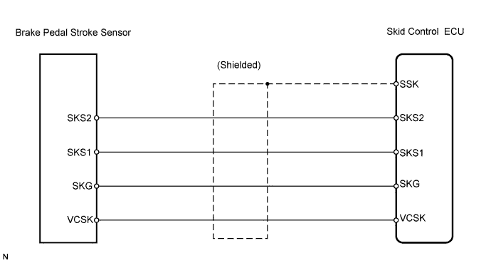
WIRING DIAGRAM


C126253E01


INSPECTION PROCEDURE

NOTICE:
When replacing the skid control ECU, perform initialization of linear solenoid valve and calibration (Click here).

1.CHECK BRAKE PEDAL
  1. Check that the brake pedal and the brake pedal stroke sensor are properly installed and that the pedal can be operated normally.

  1. Check the brake pedal height.

    OK:
    The brake pedal is securely installed.
    The pedal height is within the specified range (Click here).


NG
ADJUST BRAKE PEDAL
OK


2.READ VALUE OF TECHSTREAM (BRAKE PEDAL STROKE SENSOR)
  1. Turn the power switch ON (READY).

  1. Check the Data List for the proper functioning of the pedal stroke sensor.

    ABS / VSC / TRAC: 
    Tester Display
    Measurement Item/Range
    Normal condition
    Diagnostic Note
    Pedal Stroke Sensor 1
    Stroke sensor / Min.: 0 V, Max.: 5 V
    When brake pedal is released: 0.7 to 1.3 V
    -
    Pedal Stroke Sensor 2
    Stroke sensor 2 / Min.: 0 V, Max.: 5 V
    When brake pedal is released: 3.7 to 4.3 V
    -

    OK:
    The normal condition value displayed on Techstream.


NG
ADJUST BRAKE PEDAL STROKE SENSOR
OK


3.PERFORM INITIALIZATION OF LINEAR SOLENOID VALVE AND CALIBRATION

NEXT


4.RECONFIRM DTC
  1. Clear the DTCs (Click here).

  1. Turn the power switch ON (READY).

  1. Check the same DTCs are recorded (Click here).
    Result 
    Result
    Proceed to
    DTC is output
    A
    DTC is not output.
    B

    HINT:
    This DTC may be memorized due to a malfunction in the connector terminal connection, etc.


B
END
A


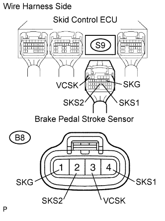
5.CHECK WIRE HARNESS (SKID CONTROL ECU - BRAKE PEDAL STROKE SENSOR)


    F047488E06
  1. Disconnect the S9 ECU connector.

  1. Disconnect the B8 sensor connector.

  1. Measure the resistance of the wire harness side connectors.

    Standard resistance:
    Tester Connection
    Specified Condition
    S9-6 (VCSK) - B8-3 (VCSK)
    Below 1 Ω
    S9-8 (SKG) - B8-1 (SKG)
    Below 1 Ω
    S9-21 (SKS1) - B8-4 (SKS1)
    Below 1 Ω
    S9-22 (SKS2) - B8-2 (SKS2)
    Below 1 Ω
    S9-6 (VCSK) - Body ground
    10 kΩ or higher
    S9-8 (SKG) - Body ground
    10 kΩ or higher
    S9-21 (SKS1) - Body ground
    10 kΩ or higher
    S9-22 (SKS2) - Body ground
    10 kΩ or higher


NG
REPAIR OR REPLACE HARNESS AND CONNECTOR
OK


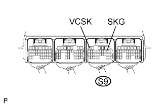
6.CHECK SKID CONTROL ECU (VCSK, SKG VOLTAGE)


    F047485E58
  1. Measure the voltage of the connector.

    HINT:
    Measure the voltage from behind the connector with the connector connected to the skid control ECU.

    Standard voltage:
    Tester Connection
    Specified Condition
    S9-6 (VCSK) - S9-8 (SKG)
    3.6 to 4.95 V


NG
REPLACE SKID CONTROL ECU
OK


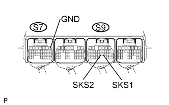
7.CHECK SKID CONTROL ECU (SKS1, SKS2 VOLTAGE)


    F047485E75
  1. Measure the voltage of the connectors.

    HINT:
    1. Measure the voltage from behind the connector with the connector connected to the skid control ECU.
    2. Slowly depress the brake pedal and check if the voltage between the skid control ECU terminals change in accordance with the pedal operation.

    Standard voltage:
    Tester Connection
    Specified Condition
    S9-21 (SKS1) - S7-1 (GND)
    1.8 to 3.1 V
    S9-22 (SKS2) - S7-1 (GND)
    1.8 to 3.1 V


NG
REPLACE BRAKE PEDAL STROKE SENSOR
OK

REPLACE SKID CONTROL ECU