 |
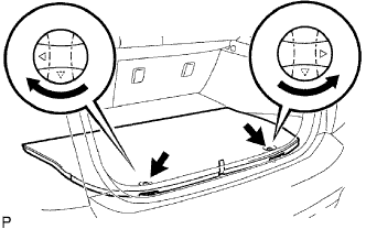
Unlock the 2 washer tank cover knobs, and then remove the rear floor board.
ENGINE ASSEMBLY > REMOVAL |
| 1. PRECAUTION |
| 2. REMOVE NO. 2 REAR FLOOR BOARD |
|
Unlock the 2 washer tank cover knobs, and then remove the rear floor board.
| 3. REMOVE REAR DECK FLOOR BOX |
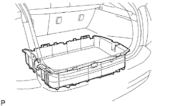 |
Remove the rear deck floor box from the vehicle.
| 4. REMOVE NO. 3 REAR FLOOR BOARD |
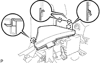 |
Detach the 4 claws, and then remove the floor board.
| 5. DISCHARGE FUEL SYSTEM PRESSURE |
Remove the integration relay (unit C: C/OPN relay) from the engine room junction block.
Start the engine. After the engine has stopped, turn the power switch off.
Check that the engine does not start.
Remove the fuel tank cap, and let the air out of the fuel tank.
Disconnect the cable from the negative (-) battery terminal.
Install the integration relay (unit C: C/OPN relay) to the engine room junction block.
| 6. DISCONNECT CABLE FROM NEGATIVE BATTERY TERMINAL |
| 7. REMOVE SERVICE PLUG GRIP |
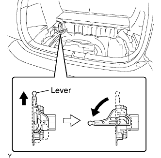 |
Slide up the lever of the service plug grip. Remove the service plug grip while turning the lever to the left.
Insulate the service plug with insulating tape.
| 8. REMOVE FRONT WHEELS |
| 9. REMOVE NO. 3 ENGINE UNDER COVER |
| 10. REMOVE NO. 4 CENTER ENGINE UNDER COVER |
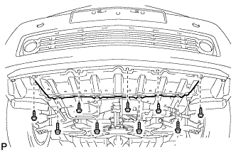 |
Remove the 5 screws, 4 bolts and under cover.
| 11. DRAIN ENGINE COOLANT |
Disconnect the coolant heat storage water pump connector.
Connect a vinyl hose to the drain cock of the radiator.
Connect a vinyl hose to the drain cock of the engine.
Connect a vinyl hose to the drain cock of the coolant heat storage tank.
Loosen the drain cock plugs of the radiator, engine and coolant heat storage tank, then drain the coolant.
Remove the radiator cap.
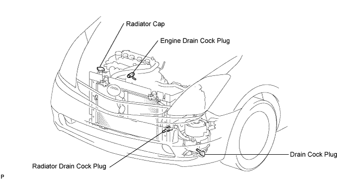
Drain the coolant in the radiator reservoir.
| 12. DRAIN TRANSAXLE OIL |
Drain the transaxle oil .
| 13. REMOVE WIPER ARM HEAD CAP |
| 14. REMOVE FRONT WIPER ARM LH |
Remove the 2 nuts and FR wiper arm LH.
| 15. REMOVE FRONT WIPER ARM RH |
Remove the nut and FR wiper arm RH.
| 16. REMOVE HOOD TO COWL TOP SEAL |
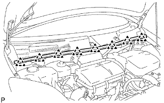 |
Detach the 8 clips and remove the hood to cowl top seal.
| 17. REMOVE COWL TOP VENTILATOR LOUVER LH |
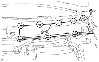 |
Detach the 8 claws and clip, and remove the cowl top ventilator louver LH.
| 18. REMOVE COWL TOP VENTILATOR LOUVER RH |
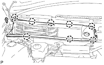 |
Detach the 8 claws and clip, and remove the cowl top ventilator louver RH.
| 19. REMOVE WINDSHIELD WIPER MOTOR AND LINK ASSEMBLY |
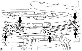 |
Disconnect the connector.
Remove the 5 bolts and wiper motor & link.
| 20. REMOVE FRONT OUTER COWL TOP PANEL |
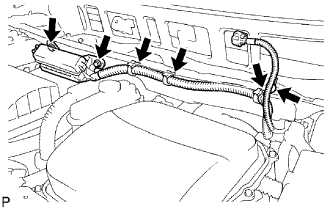 |
Remove the 2 bolts and disconnect the No. 2 engine room relay block.
Remove the 4 wire harness clamps.
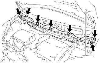 |
Remove the 7 bolts and panel.
| 21. REMOVE INVERTER WITH CONVERTER ASSEMBLY |
Remove the inverter with converter from the vehicle (Click here).
| 22. REMOVE NO. 2 RADIATOR ASSEMBLY |
Remove the No. 2 radiator from the vehicle (Click here).
| 23. DISCONNECT NO. 3 INVERTER COOLING HOSE |
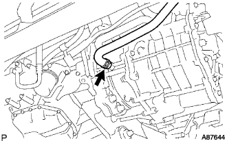 |
| 24. DISCONNECT NO. 1 HEAT STORAGE WATER BY-PASS HOSE |
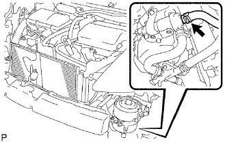 |
Disconnect the hose shown in the illustration.
| 25. DISCONNECT ENGINE WIRE |
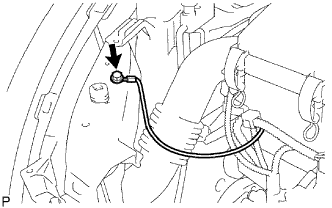 |
Remove the bolt, then disconnect the ground cable.
| 26. SEPARATE NO. 1 AIR CLEANER INLET |
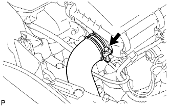 |
Loosen the clamp, then disconnect the air cleaner inlet No. 1 from the air cleaner case.
| 27. REMOVE PURGE VSV |
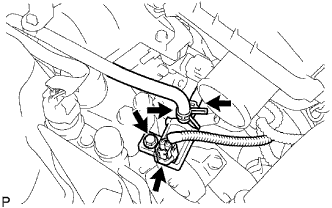 |
Disconnect the connector and hose.
Remove the bolt, then remove the vacuum switching valve assembly.
| 28. DISCONNECT FUEL TUBE |
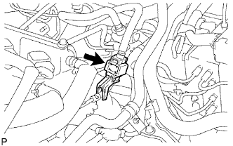 |
Remove the fuel pipe clamp.
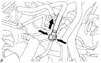 |
Disconnect the fuel tube from the fuel delivery pipe.
Cover the disconnected fuel tube and fuel delivery pipe with plastic bags in order to prevent foreign objects from entering them.
| 29. DISCONNECT HEATER WATER HOSE |
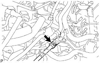 |
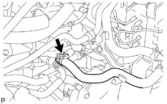
| 30. DISCONNECT NO. 3 HEAT STORAGE WATER BY-PASS HOSE |
 |
| 31. DISCONNECT ENGINE WIRE |
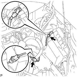 |
Disconnect the connector from the ECM, then pull the engine wire harness to the engine compartment side.
Disconnect the harness and harness clamp from the engine room main relay block.
Disconnect the ground cable.
| 32. DISCONNECT HEATER COMPRESSOR WITH MOTOR ASSEMBLY |
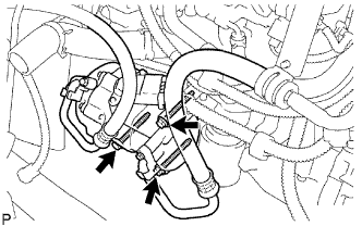 |
Disconnect the wire harness of the compressor assembly from the harness clamp.
Remove the 3 bolts, then disconnect the compressor assembly.
| 33. DISCONNECT STEERING SLIDING YOKE |
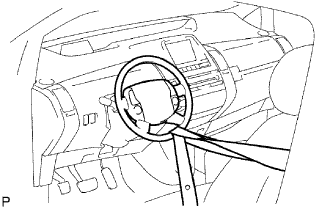 |
Install the seat belt as illustrated so that the steering wheel does not turn.
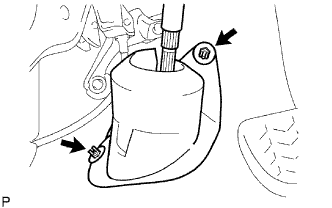 |
Remove the 2 clips, then remove the column hole cover silencer sheet.
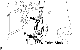 |
Loosen the bolt on the column side (A) of the sliding yoke.
Remove the bolt on the gear side (B) of the sliding yoke.
Put paint marks on the sliding yoke and intermediate shaft, and then disconnect the sliding yoke.
| 34. REMOVE FRONT EXHAUST PIPE |
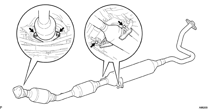
Remove the 2 bolts and 2 compression springs.
Remove the front exhaust pipe from the 2 exhaust pipe supports.
Remove the gasket from the exhaust manifold.
| 35. REMOVE FRONT AXLE HUB NUT LH |
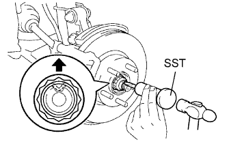 |
Using SST and a hammer, unstake the axle hub nut.
Using a 30 mm socket wrench, remove the axle hub nut.
| 36. REMOVE FRONT AXLE HUB NUT RH |
| 37. DISCONNECT FRONT STABILIZER LINK LH |
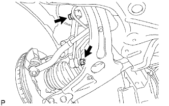 |
Remove the 2 nuts and front stabilizer link LH.
| 38. DISCONNECT TIE ROD END LH |
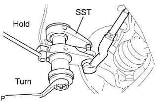 |
Remove the clip and castle nut.
Using SST, disconnect the tie rod end from the steering knuckle.
| 39. DISCONNECT TIE ROD END RH |
| 40. DISCONNECT NO. 1 FRONT SUSPENSION ARM LOWER LH |
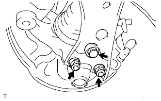 |
Remove the bolt and 2 nuts.
Push down the No. 1 front suspension lower arm and disconnect the front lower ball joint.
| 41. DISCONNECT NO. 1 FRONT SUSPENSION ARM LOWER RH |
| 42. DISCONNECT FRONT AXLE HUB LH |
Using a plastic-faced hammer, tap the end of the front drive shaft and disengage the fitting between the front drive shaft and front axle.
Push the front axle outward from the vehicle to remove the front drive shaft from the front axle.
| 43. DISCONNECT FRONT AXLE HUB RH |
| 44. REMOVE FRONT DRIVE SHAFT LH |
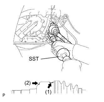 |
Remove the front fender apron seal.
Hook the SST claw at position (1) in the illustration to remove the front drive shaft.
| 45. REMOVE FRONT DRIVE SHAFT RH |
| 46. REMOVE FRONT SUSPENSION CROSSMEMBER |
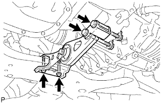 |
Remove the 4 bolts and 2 nuts, then remove the engine moving control rod with bracket.
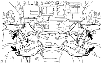 |
Remove the 4 bolts, then remove the front suspension crossmember with power steering gear assembly.
| 47. REMOVE ENGINE AND TRANSAXLE |
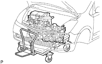 |
Set the engine lifter as illustrated.
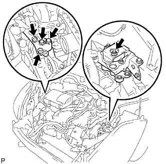 |
Remove the 2 bolts and 2 nuts, then disconnect the engine mounting bracket RH and engine mounting insulator RH.
Remove the nut, then disconnect the engine mounting insulator bracket LH and engine mounting insulator LH.
Operate the engine lifter, then remove the engine assembly with transaxle from the vehicle.
| 48. REMOVE AIR CLEANER ASSEMBLY |
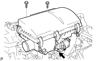 |
Disconnect the intake air flow meter connector and wire harness clamp.
Loosen the clamp, then remove the 2 bolts and air cleaner assembly.
| 49. REMOVE HYBRID VEHICLE TRANSAXLE ASSEMBLY |
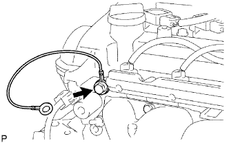 |
Remove the bolt and ground cable.
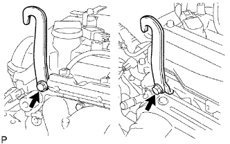 |
Install the engine hangers to the engine assembly with 2 new bolts as shown in the illustration.
Using a chain block and engine sling device, hold the engine assembly with transaxle.
Remove the engine wire harness from the engine assembly with transaxle.
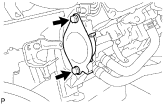 |
Remove the 2 bolts, then remove the starter hole insulator and flywheel housing side cover.
Remove the hybrid vehicle transaxle assembly from the engine assembly (Click here).
| 50. REMOVE TRANSMISSION INPUT DAMPER |
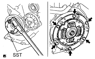 |
Using SST, hold the crankshaft.
Remove the 6 bolts, then remove the input damper and input damper cover.
| 51. REMOVE FLYWHEEL |
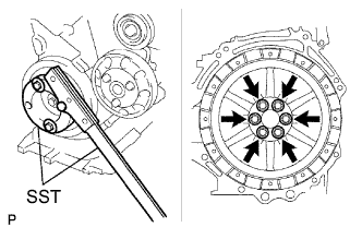 |
Using SST, hold the crankshaft.
Remove the 6 bolts and flywheel.
| 52. REMOVE OIL DIPSTICK GUIDE |
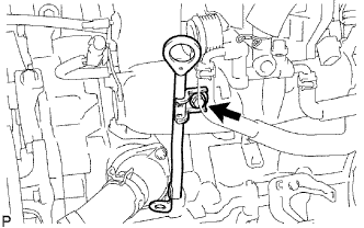 |
Remove the dipstick.
Remove the bolt and dipstick guide.
| 53. REMOVE INTAKE MANIFOLD |
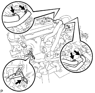 |
Remove the bolt and knock control sensor with bracket.
Disconnect the wiring harness from the bracket.
Disconnect the ventilation hose.
Disconnect the water by-pass hose.
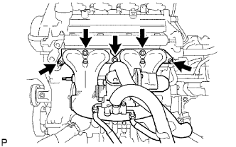 |
Remove the 3 bolts and 2 nuts, then remove the intake manifold and gasket.
| 54. REMOVE NO. 1 WATER BY-PASS PIPE |
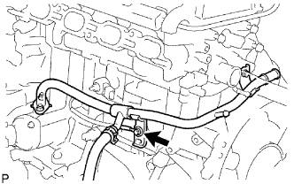 |
Remove the bolt, then disconnect the wire harness.
Remove the 2 nuts and bolt, then remove the water by-pass pipe No. 1 and gasket.
| 55. REMOVE KNOCK SENSOR |
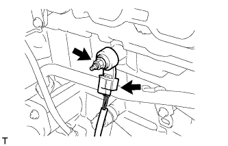 |
Disconnect the knock sensor connector.
Remove the nut and sensor.
| 56. REMOVE ENGINE OIL PRESSURE SWITCH |
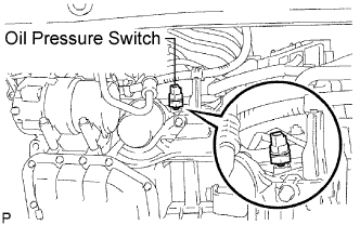 |
Remove the engine oil pressure switch assembly.
Disconnect the oil pressure switch connector.
Using a 24 mm deep socket wrench, remove the oil pressure switch.
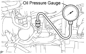 |
Install an oil pressure gauge.
Install the adaptor, then install an oil pressure gauge.
Set the vehicle to inspection mode (Click here).
Warm up the engine.
Check the oil pressure. If the oil pressure is not specified, check the oil pump (Click here).
| Condition | Specified Condition |
| Idle | 59 kPa (0.6 kgf/cm2, 4.2 psi) or more |
| 2,500 rpm | 150 to 550 kPa (1.5 to 5.6 kgf/cm2, 22 to 80 psi) |
Remove the oil pressure gauge.
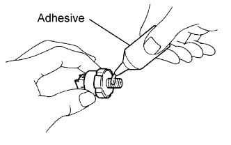 |
Install the engine oil pressure switch.
Apply adhesive to the threads.
Using a 24 mm deep socket wrench, install the oil pressure switch.
Connect the oil pressure switch connector.
| 57. REMOVE DRIVE BELT |
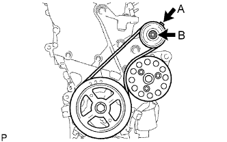 |
Loosen nut A.
Turn adjust bolt B, and then release the belt tension.
Remove the belt.
| 58. REMOVE IDLER PULLEY |
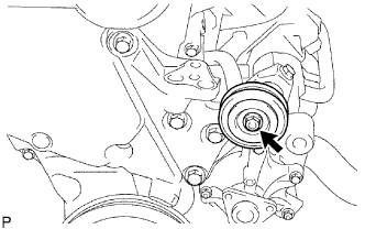 |
Remove the nut, then remove the idle pulley assembly from the engine mounting bracket RH.
| 59. REMOVE IGNITION COIL |
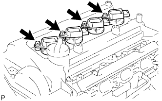 |
Remove the 4 bolts and 4 ignition coils.
| 60. REMOVE EXHAUST MANIFOLD |
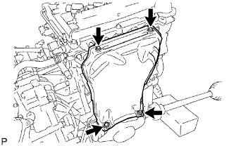 |
Remove the 4 bolts and exhaust manifold insulator.
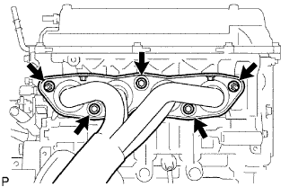 |
Remove the 3 bolts and 2 nuts, then remove the exhaust manifold.
| 61. REMOVE NOISE FILTER |
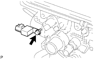 |
Remove the bolt and noise filter.
| 62. REMOVE ENGINE COOLANT TEMPERATURE SENSOR |
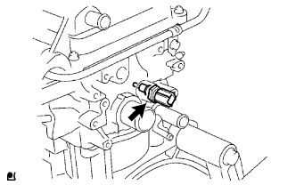 |
Using a 19 mm deep socket wrench, remove the engine coolant temperature sensor.