BRAKE SYSTEM (OTHER) BRAKE PEDAL(for LHD) REMOVAL
PROCEDURE

 1. PRECAUTION
- NOTICE:
-
After turning the power switch off, waiting time may be required before disconnecting the cable from the negative (-) auxiliary battery terminal. Therefore, make sure to read the disconnecting the cable from the negative (-) auxiliary battery terminal notices before proceeding with work (See page General>INTRODUCTION>REPAIR INSTRUCTION>PRECAUTION).
2. ALIGN FRONT WHEELS FACING STRAIGHT AHEAD
3.DISCONNECT CABLE FROM NEGATIVE AUXILIARY BATTERY TERMINAL
55404D
4.REMOVE INSTRUMENT CLUSTER FINISH PANEL SUB-ASSEMBLY
89510D
5.REMOVE BRAKE PEDAL STROKE SENSOR ASSEMBLY
84340
6.REMOVE STOP LIGHT SWITCH ASSEMBLY
84345
7.REMOVE STOP LIGHT SWITCH MOUNTING ADJUSTER
47101A
8.REMOVE BRAKE PEDAL RETURN SPRING
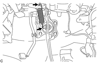
Remove the brake pedal return spring from the brake pedal support assembly and push rod pin.
45259A
9.REMOVE COLUMN HOLE COVER SILENCER SHEET
45209
10.SEPARATE STEERING SLIDING YOKE SUB-ASSEMBLY
45260
11.REMOVE NO. 2 STEERING INTERMEDIATE SHAFT ASSEMBLY
47264A
12.REMOVE PUSH ROD PIN
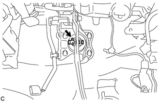
Remove the clip and push rod pin to separate the brake pedal support assembly from the push rod clevis.
13.REMOVE BRAKE PEDAL SUPPORT ASSEMBLY
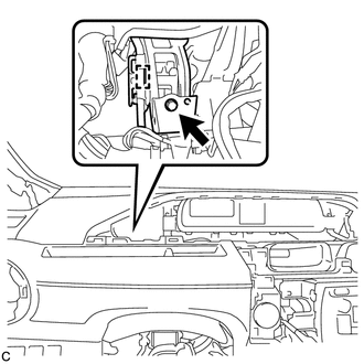
Disengage the wire harness clamp from the brake pedal support assembly.
Remove the bolt and separate the brake pedal support assembly from the instrument panel reinforcement assembly.
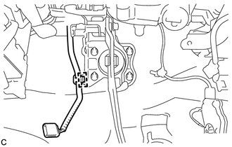
Disengage the wire harness clamp from the brake pedal support assembly.
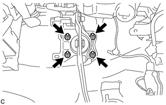
Remove the 4 nuts and brake pedal support assembly.