POWER ASSIST SYSTEMS POWER STEERING SYSTEM EPS Warning Light Circuit
DESCRIPTION
If the power steering ECU assembly detects a malfunction, the EPS warning light comes on. At this time, the power steering ECU assembly stores a DTC in its memory.
WIRING DIAGRAM
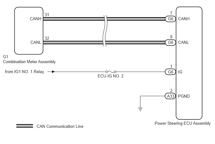
CAUTION / NOTICE / HINT
- NOTICE:
-
If the power steering ECU assembly has been replaced with a new one, perform assist map writing and torque sensor zero point calibration (See page Steering>POWER ASSIST SYSTEMS>POWER STEERING SYSTEM>CALIBRATION).
- HINT:
-
Inspect the fuses for circuits related to this system before performing the following inspection procedure.
PROCEDURE
Check for DTCs (See page Power Source / Network>NETWORKING>CAN COMMUNICATION SYSTEM>DIAGNOSIS SYSTEM).
- OK:
DTC is not output.
OK
NG
(See pagePower Source / Network>NETWORKING>CAN COMMUNICATION SYSTEM>HOW TO PROCEED WITH TROUBLESHOOTING)
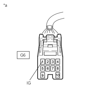
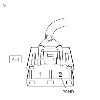
Disconnect the connectors from the power steering ECU assembly.
Measure the voltage according to the value(s) in the table below.
- Standard Voltage:
Tester Connection Condition Specified Condition G6-1 (IG) - Body ground Power switch on (IG) 9 to 16 V
Measure the resistance according to the value(s) in the table below.
- Standard Resistance:
Tester Connection Condition Specified Condition A33-2 (PGND) - Body ground Always Below 1 Ω
| *a | Front view of wire harness connector
(to Power Steering ECU Assembly) |
OK
NG
Reconnect the power steering ECU assembly connector.
Perform the Active Test of the combination meter assembly using the intelligent tester (See page Vehicle Interior>METER / GAUGE / DISPLAY>METER / GAUGE SYSTEM>DATA LIST / ACTIVE TEST).
Check the combination meter assembly.
- OK:
The EPS warning light turns on or off in accordance with the intelligent tester operation.
- HINT:
-
If troubleshooting has been carried out according to Problem Symptoms Table, refer back to the table and proceed to the next step before replacing the part (See page Steering>POWER ASSIST SYSTEMS>POWER STEERING SYSTEM>PROBLEM SYMPTOMS TABLE).
OK
NG