METER / GAUGE / DISPLAY METER / GAUGE SYSTEM B1504 Lost Communication with Steering SW
DESCRIPTION
The combination meter assembly communicates with the steering pad switch assembly via a direct line . If the combination meter assembly detects a communication malfunction, it stores this DTC.
| DTC No. | DTC Detection Condition | Trouble Area |
|---|---|---|
| B1504 | When the IG voltage is 9.5 V or more and power switch on (IG) and the following condition is detected:
1.
Steering pad switch assembly communication error has been detected more than 3 seconds. |
·
Harness or connector ·
Spiral cable ·
Steering pad switch RH ·
Steering pad switch LH ·
Combination meter assembly |
WIRING DIAGRAM
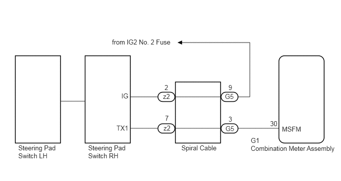
CAUTION / NOTICE / HINT
- HINT:
-
Before starting the following inspection, confirm the (steering pad switch assembly) setting.
PROCEDURE
Connect the intelligent tester to the DLC3.
Turn the power switch on (IG).
Turn the intelligent tester on.
Enter the following menus: Body / Combination Meter / Data List.
Check the values by referring to the table below.
| Tester Display | Measurement Item/Range | Normal Condition | Diagnostic Note |
|---|---|---|---|
| Multi Display Select Switch | DISP switch in the steering pad switch assembly/OFF or ON | OFF: DISP switch in the steering pad switch assembly not pressed | - |
| ON: DISP switch in the steering pad switch assembly pressed | - | ||
| Drive Monitor Reset SW | TRIP switch in the steering pad switch assembly/OFF or ON | OFF: TRIP switch in the steering pad switch assembly not pressed | - |
| ON: TRIP switch in the steering pad switch assembly pressed more than 1 second | - |
- OK:
Steering pad switch assembly condition displayed on the intelligent tester changes with the actual switch operation.
OK
NG
Check the spiral cable (See page Vehicle Interior>SUPPLEMENTAL RESTRAINT SYSTEMS>SPIRAL CABLE>INSPECTION).
OK
NG
Disconnect the G1 combination meter assembly connector.
Disconnect the z2 steering pad switch RH connector.
Measure the voltage according to the value(s) in the table below.
- Standard Voltage:
Tester Connection Condition Specified Condition z2-2 - Body ground Power switch off Below 1 V z2-2 - Body ground Power switch on (IG) 11 to 14 V
Measure the resistance according to the value(s) in the table below.
- Standard Resistance:
Tester Connection Condition Specified Condition z2-7 - G1-30 (MSFM) Always Below 1 Ω G1-30 (MSFM) - Body ground Always 10 kΩ or higher
OK
NG
Replace the steering pad switch RH with a new or a known good one (See page Steering>STEERING COLUMN>STEERING PAD SWITCH>REMOVAL).
- OK:
The operation of the combination meter assembly returns to normal.
OK
NG
Replace the steering pad switch LH with a new or a known good one (See page Steering>STEERING COLUMN>STEERING PAD SWITCH>REMOVAL).
- OK:
The operation of the combination meter assembly returns to normal.
OK
NG