INTERIOR PANELS / TRIM UPPER INSTRUMENT PANEL REMOVAL
PROCEDURE

 1. PRECAUTION
(See page Vehicle Interior>INTERIOR PANELS / TRIM>UPPER INSTRUMENT PANEL>PRECAUTION)
- NOTICE:
-
After turning the power switch off, waiting time may be required before disconnecting the cable from the auxiliary battery negative (-) terminal. Therefore, make sure to read the disconnecting the cable from the auxiliary battery negative (-) terminal notices before proceeding with work (See page General>INTRODUCTION>REPAIR INSTRUCTION>PRECAUTION)
58165F
2.REMOVE FRONT FLOOR COVER RH
3.DISCONNECT CABLE FROM NEGATIVE AUXILIARY BATTERY TERMINAL
- CAUTION:
-
Wait at least 90 seconds after disconnecting the cable from the auxiliary battery negative (-) terminal to disable the SRS system.
- NOTICE:
-
When disconnecting the cable, some systems need to be initialized after the cable is reconnected (See page General>INTRODUCTION>REPAIR INSTRUCTION>INITIALIZATION).
55405B
4.REMOVE CENTER INSTRUMENT CLUSTER FINISH PANEL SUB-ASSEMBLY
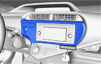
Apply protective tape to the area shown in the illustration.
| *1 | Protective Tape |
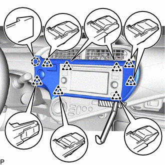
Using a moulding remover, disengage the 8 clips and claw.
- NOTICE:
-
Do not use a moulding remover to an area other than that shown in the illustration. Using a moulding remover in an area other than that shown in the illustration may result in deformation or damage to related parts.
Disconnect the connector and remove the center instrument cluster finish panel sub-assembly.
55660
5.REMOVE NO. 2 INSTRUMENT PANEL REGISTER ASSEMBLY (for LHD)
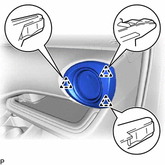
Disengage the 3 clips and remove the No. 2 instrument panel register assembly.
55650
6.REMOVE NO. 1 INSTRUMENT PANEL REGISTER ASSEMBLY (for RHD)
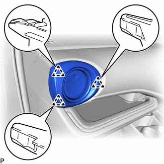
Disengage the 3 clips and remove the No. 1 instrument panel register assembly.
55474B
7.REMOVE INSTRUMENT CLUSTER FINISH PANEL GARNISH
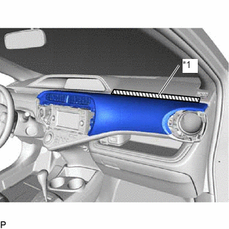
Apply protective tape to the area shown in the illustration.
| *1 | Protective Tape |
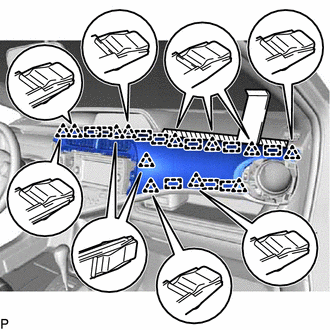
Using a moulding remover, disengage the 12 clips and 10 guides to remove the instrument cluster finish panel garnish.
55670A
8.REMOVE CENTER INSTRUMENT PANEL REGISTER ASSEMBLY
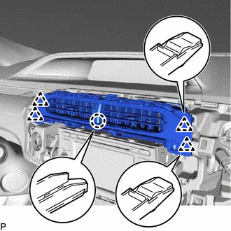
Disengage the claw and 4 clips to remove the center instrument panel register assembly.
55404D
9.REMOVE INSTRUMENT CLUSTER FINISH PANEL SUB-ASSEMBLY
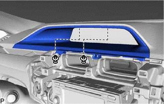
Using a clip remover, remove the 2 clips.
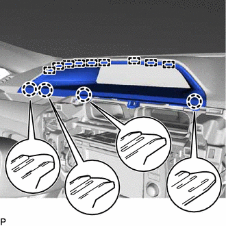
Disengage the 4 claws and 9 guides and remove the instrument cluster finish panel sub-assembly.
83100
10.REMOVE COMBINATION METER ASSEMBLY
62312B
11.DISCONNECT FRONT DOOR OPENING TRIM WEATHERSTRIP LH
Disconnect the front door opening trim weatherstrip LH.
62212
12.REMOVE FRONT PILLAR GARNISH LH
62311B
13.DISCONNECT FRONT DOOR OPENING TRIM WEATHERSTRIP RH
Disconnect the front door opening trim weatherstrip RH.
62211
14.REMOVE FRONT PILLAR GARNISH RH
- HINT:
-
Use the same procedure as for the LH side.
82142A
15.DISCONNECT NO. 2 INSTRUMENT PANEL WIRE
16.REMOVE UPPER INSTRUMENT PANEL ASSEMBLY
Remove the bolt <A>.
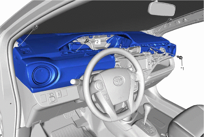
| *1 | Bolt <A> | *2 | Screw <C> |
Remove the screw <C>.
Using a clip remover, remove the 2 clips.
Pull the upper instrument panel assembly in the direction indicated by the arrow (1) to disengage the 7 clips.
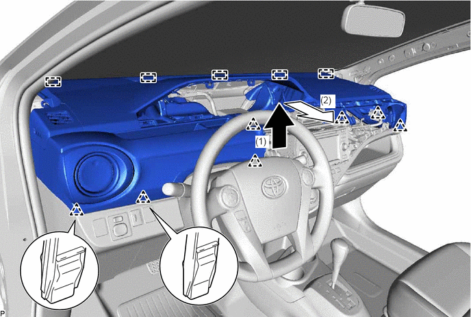
Pull the upper instrument panel assembly in the direction indicated by the arrow (2) to disengage the 5 guides and remove the upper instrument panel assembly.