DOOR / HATCH REAR DOOR DISASSEMBLY
CAUTION / NOTICE / HINT
- HINT:
- ·
Use the same procedure for the RH side and LH side.
·The procedure described below is for the LH side.
PROCEDURE

 1. PRECAUTION
- NOTICE:
-
After turning the power switch off, waiting time may be required before disconnecting the cable from the negative (-) auxiliary battery terminal. Therefore, make sure to read the disconnecting the cable from the negative (-) auxiliary battery terminal notice before proceeding with work (See page General>INTRODUCTION>REPAIR INSTRUCTION>PRECAUTION).
58165F
2.REMOVE FRONT FLOOR COVER RH
3.DISCONNECT CABLE FROM NEGATIVE AUXILIARY BATTERY TERMINAL
- NOTICE:
-
When disconnecting the cable, some systems need to be initialized after the cable is reconnected (See page General>INTRODUCTION>REPAIR INSTRUCTION>INITIALIZATION).
67674A
4.REMOVE REAR DOOR FRAME GARNISH
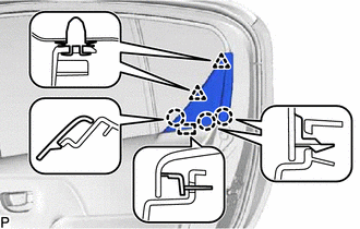
Disengage the 2 clips and 3 claws.
Disengage the guide and remove the rear door frame garnish.
5.REMOVE REAR POWER WINDOW REGULATOR SWITCH ASSEMBLY WITH REAR DOOR ARMREST BASE PANEL
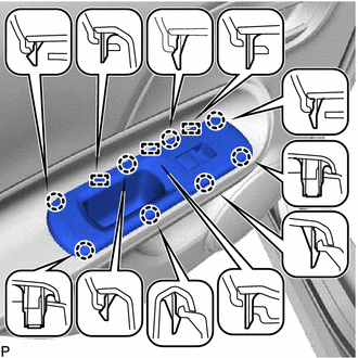
Disengage the 8 claws and 3 guides.
Disconnect the connector and remove the rear power window regulator switch assembly with rear door armrest base panel.
67604
6.REMOVE REAR DOOR TRIM BOARD SUB-ASSEMBLY
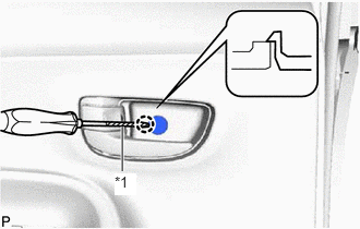
Using a screwdriver with its tip wrapped in protective tape, disengage the claw and open the cover.
| *1 | Protective Tape |
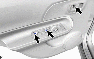
Remove the 3 screws.
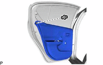
Disengage the clip.
pull the rear door trim board sub-assembly at the position indicated in the illustration and disengage the 7 clips in the order shown in the illustration.
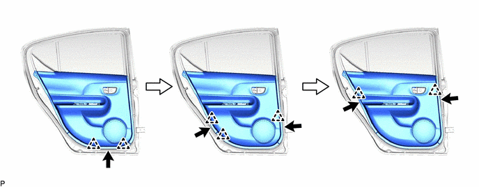
- NOTICE:
-
Do not apply excessive force when pulling the rear door trim board sub-assembly.
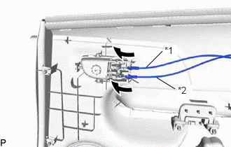
Disconnect the rear door lock remote control cable assembly and rear door inside locking cable assembly and remove the rear door trim board.
| *1 | Rear Door Inside Locking Cable Assembly |
| *2 | Rear Door Lock Remote Control Cable Assembly |
69206C
7.REMOVE REAR DOOR INSIDE HANDLE SUB-ASSEMBLY
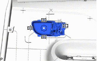
Disengage the 4 guides and remove the rear door inside handle sub-assembly.
68174A
8.REMOVE REAR DOOR GLASS INNER WEATHERSTRIP
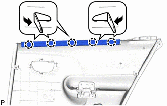
Disengage the 5 claws and remove the rear door glass inner weatherstrip as shown in the illustration.
86160B
9.REMOVE REAR SPEAKER ASSEMBLY
67842E
10.REMOVE REAR DOOR SERVICE HOLE COVER
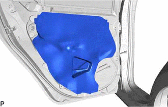
Remove the rear door service hole cover.
- NOTICE:
-
Remove any tape remaining on the door side.
68630
11.REMOVE REAR DOOR CHECK ASSEMBLY
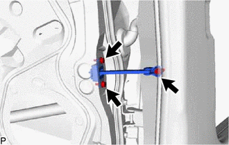
Remove the 3 bolts and the rear door check assembly.
67872
12.REMOVE REAR DOOR WEATHERSTRIP
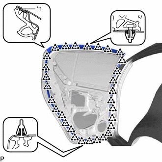
Using a clip remover, disengage the 30 clips.
| *1 | Double-sided Tape |
Remove the rear door weatherstrip.
68152C
13.REMOVE REAR DOOR GLASS RUN
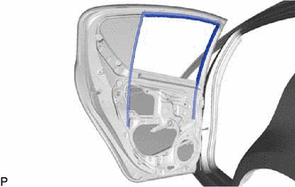
Remove the rear door glass run.
67408E
14.REMOVE REAR DOOR WINDOW DIVISION BAR SUB-ASSEMBLY
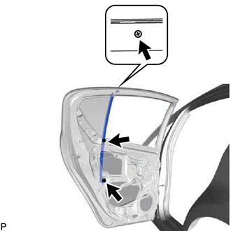
Remove the 2 bolts and screw, and remove the rear door window division bar sub-assembly.
68104
15.REMOVE REAR DOOR GLASS SUB-ASSEMBLY
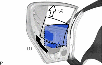
Slide the lower section of the rear door glass and disengage the rear door glass from the rear window regulator sub-assembly.
Remove the rear door glass sub-assembly as indicated by the arrows in the order shown in the illustration.
- NOTICE:
-
Do not damage the rear door glass.
69906B
16.REMOVE REAR DOOR GLASS CHANNEL SUB-ASSEMBLY
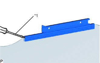
Using a screwdriver with its tip wrapped in protective tape, remove the rear door glass channel sub-assembly.
| *1 | Protective Tape |
- NOTICE:
-
Do not damage the rear door glass.
69975A
17.REMOVE REAR DOOR GLASS CHANNEL FILLER
Remove the rear door glass channel filler.
18.REMOVE REAR DOOR WINDOW REGULATOR ASSEMBLY
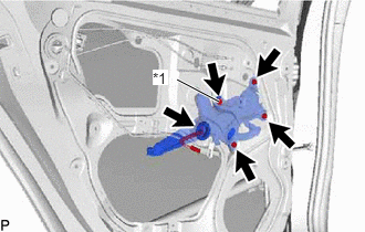
Disconnect the connector.
| *1 | Temporary Bolt |
Loosen the temporary bolt.
- NOTICE:
-
Do not remove the temporary bolt. If the temporary bolt is removed, the rear door window regulator assembly may fall and cause damage.
Remove the 3 bolts and rear door window regulator assembly.
Remove the temporary bolt from the rear door window regulator assembly.
85720E
19.REMOVE POWER WINDOW REGULATOR MOTOR ASSEMBLY
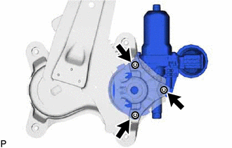
Using a T25 "TORX" socket wrench, remove the 3 screws and power window regulator motor assembly.
68230C
20.REMOVE REAR DOOR GLASS OUTER WEATHERSTRIP ASSEMBLY
68124B
21.REMOVE REAR DOOR QUARTER WINDOW GLASS
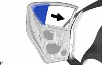
Slide the rear door quarter window glass as shown in the illustration and remove the rear door quarter window glass with rear door quarter window weatherstrip.
69340
22.REMOVE REAR DOOR LOCK ASSEMBLY
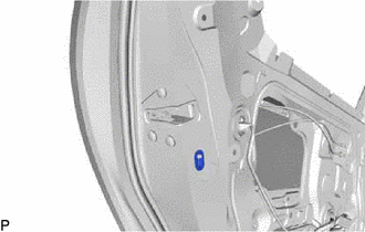
Remove the rear door lock child protection cover.
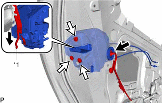
Disconnect the connector.
Using a T30 "TORX" socket wrench, remove the 3 screws.
Move the rear door lock assembly downward and pull the release plate out of the rear door outside handle frame.
| *1 | Release Plate |
When reusing the rear door lock assembly:
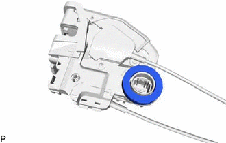
Remove the door lock wiring harness seal from the rear door lock assembly.
69740D
23.REMOVE REAR DOOR LOCK REMOTE CONTROL CABLE ASSEMBLY
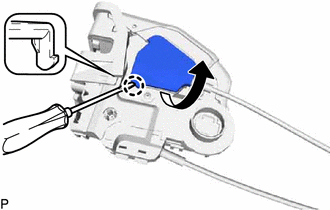
Using a screwdriver, disengage the claw as shown in the illustration.
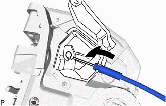
Remove the rear door lock remote control cable assembly as shown in the illustration.
69780B
24.REMOVE REAR DOOR INSIDE LOCKING CABLE ASSEMBLY
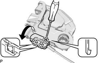
Using a screwdriver, disengage the 3 claws as shown in the illustration.
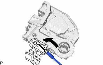
Remove the rear door inside locking cable assembly as shown in the illustration.
69227L
25.REMOVE REAR DOOR OUTSIDE HANDLE COVER
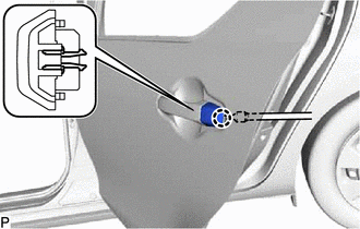
Using a "TORX" socket wrench T30, loosen the screw.
- HINT:
-
The screw cannot be removed because it is integrated into the rear door outside handle frame sub-assembly.
Disengage the claw and remove the rear door outside handle cover.
69240
26.REMOVE REAR DOOR OUTSIDE HANDLE ASSEMBLY
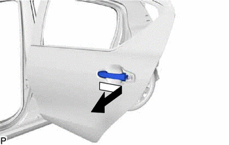
Remove the rear door outside handle assembly as shown in the illustration.
69241G
27.REMOVE REAR DOOR OUTSIDE HANDLE FRONT PAD
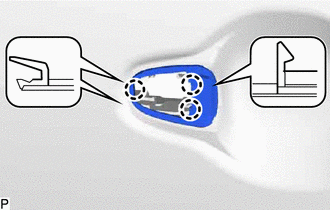
Disengage the 3 claws to remove the rear door outside handle front pad.
69242G
28.REMOVE REAR DOOR OUTSIDE HANDLE REAR PAD
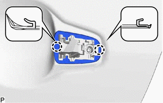
Disengage the 2 claws to remove the rear door outside handle rear pad.
69204A
29.REMOVE REAR DOOR OUTSIDE HANDLE FRAME SUB-ASSEMBLY
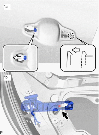
Using a T30 "TORX" socket wrench, loosen the screw.
| *a | Outside |
| *b | Inside |
Slide the rear door outside handle frame sub-assembly to disengage the door handle nut and claw of the rear door outside handle frame sub-assembly, and then remove the rear door outside handle frame sub-assembly.
75924
30.REMOVE NO. 2 BLACK OUT TAPE