Home › Engine / Hybrid System › 2ZR-FXE (ENGINE CONTROL) › SFI SYSTEM › 2012.03–2014.11
RM2070E _51 Engine / Hybrid System _061905 2ZR-FXE ENGINE CONTROL _0301559 SFI SYSTEM J

2ZR-FXE ENGINE CONTROL  SFI SYSTEM  Fuel Pump Control Circuit  


DESCRIPTION

When the NE signal is input to the ECM, Tr is turned on, current flows to the coil of the circuit opening relay, the relay switches on, power is supplied to the fuel pump and the fuel pump operates.

While the NE signal is generated (engine running), the ECM keeps Tr on (C/OPN relay on) and the fuel pump also keeps operating.
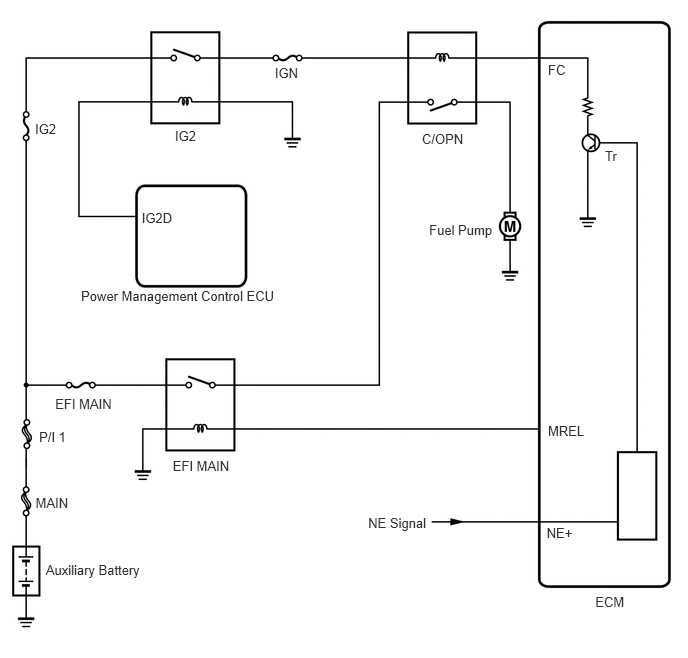
A217608E05
2.863,0.679 3.154,0.821 0.290,0.142 10 IGN 1.822,1.333 2.112,1.475 0.290,0.142 10 IG2 1.476,2.183 1.827,2.325 0.350,0.142 10 IG2D 0.365,1.258 0.655,1.400 0.290,0.142 10 IG2 0.844,3.005 3.208,3.379 2.365,0.373 10 Power Management Control ECU 1.799,4.766 2.474,4.908 0.675,0.142 10 EFI MAIN 0.575,4.121 1.212,4.277 0.637,0.156 10 EFI MAIN 0.407,4.467 0.797,4.632 0.390,0.165 10 P/I 1 0.37,5.152 0.947,5.294 0.577,0.142 10 MAIN 0.477,5.857 1.522,5.999 1.045,0.142 10 Auxiliary Battery 3.835,5.362 4.495,5.518 0.661,0.156 10 NE Signal 4.395,1.361 4.861,1.503 0.466,0.142 10 C/OPN 4.47,2.309 5.181,2.460 0.711,0.151 10 Fuel Pump 5.708,0.642 5.924,0.789 0.216,0.147 10 FC 6.301,1.543 6.466,1.690 0.165,0.147 10 Tr 5.708,4.411 6.123,4.571 0.415,0.161 10 MREL 5.694,5.469 6.011,5.616 0.318,0.147 10 NE+ 6.201,6.189 6.540,6.335 0.339,0.147 10 ECM

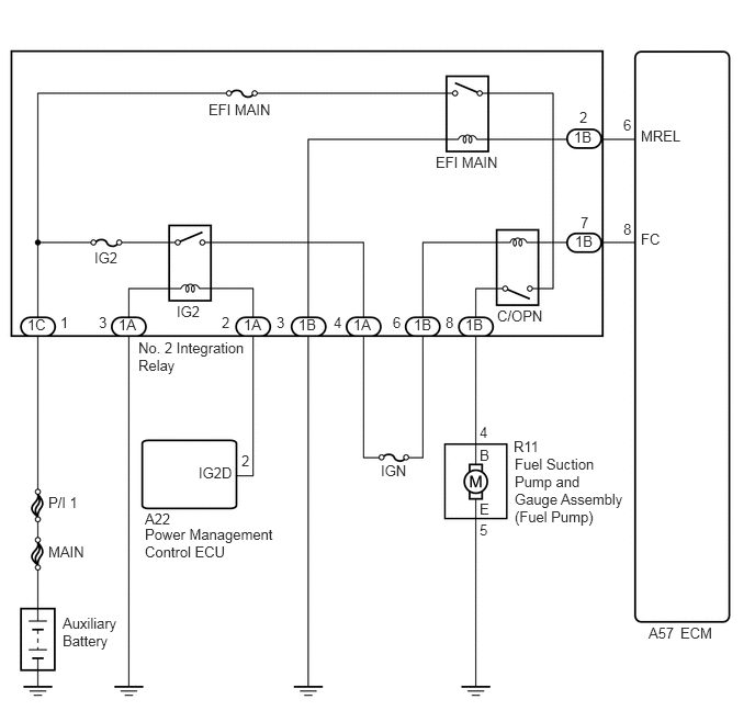
WIRING DIAGRAM

A280603E05
3.615,4.385 3.906,4.531 0.292,0.146 10 false IGN 1.677,2.875 1.969,3.021 0.292,0.146 10 false IG2 1.885,4.406 2.24,4.552 0.354,0.146 10 false IG2D 0.896,2.365 1.188,2.51 0.292,0.146 10 false IG2 1.375,4.99 2.719,5.302 1.344,0.313 10 false Power Management Control ECU 1.979,0.958 2.656,1.104 0.677,0.146 10 false EFI MAIN 4.135,1.458 4.813,1.604 0.677,0.146 10 false EFI MAIN 0.458,4.688 0.844,4.854 0.385,0.167 10 false P/I 1 0.458,5.156 1.031,5.302 0.573,0.146 10 false MAIN 0.594,5.833 1.146,6.188 0.552,0.354 10 false Auxiliary Battery 4.719,2.917 5.188,3.063 0.469,0.146 10 false C/OPN 4.885,4.323 5.938,5.083 1.052,0.76 10 false Fuel Suction Pump and Gauge Assembly (Fuel Pump) 6.083,2.188 6.302,2.333 0.219,0.146 10 false FC 6.458,5.927 6.802,6.073 0.344,0.146 10 false ECM 1.375,4.844 1.667,5.042 0.292,0.198 10 false A22 4.552,4.021 4.74,4.198 0.188,0.177 10 false 4 4.552,4.24 4.74,4.417 0.188,0.177 10 false B 4.552,4.75 4.74,4.927 0.188,0.177 10 false E 4.552,4.948 4.74,5.177 0.188,0.229 10 false 5 4.875,4.156 5.198,4.354 0.323,0.198 10 false R11 6.156,5.927 6.479,6.104 0.323,0.177 10 false A57 0.26,3 0.5,3.198 0.24,0.198 10 false 1C 1.125,3 1.365,3.198 0.24,0.198 10 false 1A 2.833,3 3.073,3.198 0.24,0.198 10 false 1B 3.354,3 3.594,3.198 0.24,0.198 10 false 1A 3.927,3 4.167,3.198 0.24,0.198 10 false 1B 4.417,3 4.656,3.198 0.24,0.198 10 false 1B 5.458,2.208 5.698,2.365 0.24,0.156 10 false 1B 5.448,1.219 5.688,1.417 0.24,0.198 10 false 1B 2.292,4.292 2.438,4.458 0.146,0.167 10 false 2 5.5,1.031 5.677,1.188 0.177,0.156 10 false 2 5.917,1.104 6.094,1.26 0.177,0.156 10 false 6 5.917,2.094 6.094,2.25 0.177,0.156 10 false 8 5.51,2.031 5.688,2.188 0.177,0.156 10 false 7 6.083,1.208 6.583,1.354 0.5,0.146 10 false MREL 0.573,2.979 0.719,3.177 0.146,0.198 10 false 1 0.938,2.979 1.083,3.177 0.146,0.198 10 false 3 2.625,2.979 2.771,3.177 0.146,0.198 10 false 3 2.313,3 2.552,3.198 0.24,0.198 10 false 1A 2.104,2.979 2.25,3.177 0.146,0.198 10 false 2 3.167,2.979 3.313,3.177 0.146,0.198 10 false 4 3.729,2.979 3.875,3.177 0.146,0.198 10 false 6 4.229,2.979 4.375,3.177 0.146,0.198 10 false 8 1.313,3.219 2.344,3.583 1.031,0.365 10 false No. 2 Integration Relay

CAUTION / NOTICE / HINT

NOTICE:

Inspect the fuses for circuits related to this system before performing the following inspection procedure.


PROCEDURE

1.PERFORM ACTIVE TEST USING GTS (OPERATE C/OPN RELAY)
a.

Connect the GTS to the DLC3.


b.

Turn the power switch on (IG).


c.

Turn the GTS on.


d.

Enter the following menus: Powertrain / Engine and ECT / Active Test / Control the Fuel Pump / Speed.


e.

Check whether the fuel pump operation sound occurs when performing the Active Test on the GTS.

OK:

Fuel pump operating sound occurs.


OK

PROCEED TO NEXT SUSPECTED AREA SHOWN IN PROBLEM SYMPTOMS TABLE

NG

2.INSPECT NO. 2 INTEGRATION RELAY (C/OPN RELAY)
a.

Inspect the No. 2 integration relay (C/OPN relay) (See page Engine / Hybrid System>2ZR-FXE (ENGINE CONTROL)>INTEGRATION RELAY>INSPECTION).


OK

3.CHECK HARNESS AND CONNECTOR (NO. 2 INTEGRATION RELAY (C/OPN RELAY) - ECM)

NG

3.CHECK HARNESS AND CONNECTOR (NO. 2 INTEGRATION RELAY (C/OPN RELAY) - ECM)
a.

Disconnect the ECM connector.


b.

Remove the No. 2 integration relay (C/OPN relay) from the engine room relay block and junction block assembly.


c.

Disconnect the No. 2 integration relay connector.


d.

Measure the resistance according to the value(s) in the table below.

Standard Resistance:
Tester Connection Condition Specified Condition
1B-7 - A57-8 (FC) Always Below 1 Ω
1B-7 or A57-8 (FC) - Body ground Always 10 kΩ or higher


OK

4.CHECK HARNESS AND CONNECTOR (NO. 2 INTEGRATION RELAY (C/OPN RELAY - IG2 RELAY))

NG

REPAIR OR REPLACE HARNESS OR CONNECTOR

4.CHECK HARNESS AND CONNECTOR (NO. 2 INTEGRATION RELAY (C/OPN RELAY - IG2 RELAY))
a.

Remove the No. 2 integration relay (C/OPN relay and IG2 relay) from the engine room relay block and junction block assembly.


b.

Disconnect the No. 2 integration relay connector.


c.

Measure the resistance according to the value(s) in the table below.

Standard Resistance:
Tester Connection Condition Specified Condition
1B-6 - 1A-4 Always Below 1 Ω


OK

5.CHECK HARNESS AND CONNECTOR (NO. 2 INTEGRATION RELAY (C/OPN RELAY) - FUEL PUMP)

NG

REPAIR OR REPLACE HARNESS OR CONNECTOR

5.CHECK HARNESS AND CONNECTOR (NO. 2 INTEGRATION RELAY (C/OPN RELAY) - FUEL PUMP)
a.

Disconnect the fuel pump connector.


b.

Remove the No. 2 integration relay (C/OPN relay) from the engine room relay block and junction block assembly.


c.

Disconnect the No. 2 integration relay connector.


d.

Measure the resistance according to the value(s) in the table below.

Standard Resistance:
Tester Connection Condition Specified Condition
1B-8 - R11-4 (B) Always Below 1 Ω
1B-8 or R11-4 (B) - Body ground Always 10 kΩ or higher


OK

6.CHECK HARNESS AND CONNECTOR (FUEL PUMP - BODY GROUND)

NG

REPAIR OR REPLACE HARNESS OR CONNECTOR

6.CHECK HARNESS AND CONNECTOR (FUEL PUMP - BODY GROUND)
a.

Disconnect the fuel pump connector.


b.

Measure the resistance according to the value(s) in the table below.

Standard Resistance:
Tester Connection Condition Specified Condition
R11-5 (E) - Body ground Always Below 1 Ω


OK

7.INSPECT FUEL PUMP

NG

REPAIR OR REPLACE HARNESS OR CONNECTOR

7.INSPECT FUEL PUMP
a.


OK

8.CHECK ECM POWER SOURCE CIRCUIT

NG

8.CHECK ECM POWER SOURCE CIRCUIT

OK

NG

REPAIR OR REPLACE ECM POWER SOURCE CIRCUIT