HYBRID / BATTERY CONTROL FRAME WIRE INSTALLATION
PROCEDURE

 82164
1.INSTALL FRAME WIRE
- CAUTION:
-
Wear insulated gloves.
Install the frame wire with 3 new clamps.
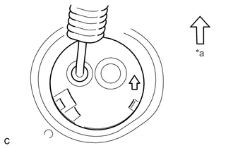
Insert the frame wire into the floor panel hole.
| *a | Front of Vehicle |
- HINT:
-
The arrow should be pointing toward the front of the vehicle.
Install the 3 nuts.
- Torque:
- 8.4 N*m (86 kgf*cm, 74 in.*lbf)
Install the bolt.
- Torque:
- 8.4 N*m (86 kgf*cm, 74 in.*lbf)
Install the nut and clamp.
- Torque:
- 8.4 N*m (86 kgf*cm, 74 in.*lbf)
Install the nut and 2 clamps.
- Torque:
- 8.4 N*m (86 kgf*cm, 74 in.*lbf)
Install the heater water pipe sub-assembly with the nut.
- Torque:
- 9.8 N*m (100 kgf*cm, 87 in.*lbf)
Connect the 4 clamps.
Connect the connector to the engine room junction block assembly.
Engage the 3 claws.
Connect the 4 wire harness clamps to the floor panel.
Connect the clamp to the floor panel to install the wire harness protector.
Install the floor carpet with the 2 clips.
G92Z0
2.CONNECT HYBRID BATTERY JUNCTION BLOCK ASSEMBLY
- CAUTION:
-
Wear insulated gloves.
Install the frame wire on the hybrid battery junction block assembly with the 3 nuts.
- Torque:
- 9.0 N*m (92 kgf*cm, 80 in.*lbf)
- NOTICE:
- ·
Make sure that the ends of the frame wire are not crossed over each other.
·Be sure to connect the ends of the frame wire to the connect terminals.
3.CONNECT CABLE TO POSITIVE AUXILIARY BATTERY TERMINAL
Connect the 4 clamps.
Install the nut.
- Torque:
- 5.4 N*m (55 kgf*cm, 48 in.*lbf)
Install the terminal cover.
64730B
4.INSTALL DECK TRIM SIDE PANEL ASSEMBLY RH
- HINT:
-
Use the same procedure as for the LH side (See page Vehicle Interior>INTERIOR PANELS / TRIM>ROOF HEADLINING>INSTALLATION).
55548C
5.INSTALL NO. 1 CUP HOLDER
64712F
6.INSTALL FRONT DECK SIDE TRIM COVER RH
- HINT:
-
Use the same procedure as for the LH side (See page Vehicle Interior>INTERIOR PANELS / TRIM>ROOF HEADLINING>INSTALLATION).
58460D
7.INSTALL LUGGAGE HOLD BELT STRIKER ASSEMBLY (for RH Side)
- HINT:
-
Use the same procedure as for the LH side (See page Vehicle Interior>INTERIOR PANELS / TRIM>ROOF HEADLINING>INSTALLATION).
64721G
8.INSTALL NO. 1 DECK TRIM COVER (for RH Side)
- HINT:
-
Use the same procedure as for the LH side (See page Vehicle Interior>INTERIOR PANELS / TRIM>ROOF HEADLINING>INSTALLATION).
73560
9.CONNECT REAR NO. 2 SEAT OUTER BELT ASSEMBLY RH
73360C
10.CONNECT REAR NO. 1 SEAT OUTER BELT ASSEMBLY RH
67935A
11.INSTALL BACK DOOR SCUFF PLATE
12.INSTALL REAR NO. 2 SEAT ASSEMBLY
13.INSTALL REAR NO. 1 SEAT ASSEMBLY (for Center)
14.INSTALL REAR NO. 1 SEAT ASSEMBLY (for Side)
64910J
15.INSTALL TONNEAU COVER ASSEMBLY (w/ Tonneau Cover)
52257
16.INSTALL FRONT SUSPENSION MEMBER REAR BRACE RH
Using a transmission jack, hold the front suspension cross member.
- NOTICE:
-
Be sure to position the transmission jack to properly support the front suspension cross member.
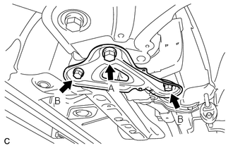
Remove the bolt A
Install the front suspension member rear brace RH with the 2 bolts B and bolt A.
- Torque:
- Bolt A : 137 N*m (1397 kgf*cm, 101 ft.*lbf)
- Bolt B : 93 N*m (948 kgf*cm, 69 ft.*lbf)
58151
17.INSTALL FRONT NO. 1 FLOOR HEAT INSULATOR
Install the No. 1 front floor heat insulator with the 3 nuts.
- Torque:
- 5.5 N*m (56 kgf*cm, 49 in.*lbf)
17410
18.INSTALL FRONT EXHAUST PIPE ASSEMBLY
G9200
19.INSTALL INVERTER WITH CONVERTER ASSEMBLY
G920Q
20.INSTALL NO. 1 HYBRID BATTERY SHIELD SUB-ASSEMBLY
58810J
21.INSTALL CONSOLE BOX ASSEMBLY
58817A
22.INSTALL FRONT NO. 2 CONSOLE BOX INSERT
58804A
23.INSTALL UPPER CONSOLE PANEL SUB-ASSEMBLY
58534H
24.INSTALL CENTER FLOOR CARPET COVER LH
58533F
25.INSTALL CENTER FLOOR CARPET COVER RH
G3834
26.INSTALL SERVICE PLUG GRIP