2ZR-FXE INTAKE / EXHAUST EXHAUST MANIFOLD INSTALLATION
PROCEDURE

 17168
1.INSTALL NO. 2 EXHAUST MANIFOLD HEAT INSULATOR
Install the No. 2 exhaust manifold heat insulator with the 3 bolts.
- Torque:
- 12 N*m (122 kgf*cm, 9 ft.*lbf)
17141
2.INSTALL EXHAUST MANIFOLD
Install 2 new gaskets.
Temporarily install the exhaust manifold and manifold stay with the 7 nuts and 3 bolts.
- HINT:
-
The type B and type C are non-reusable.
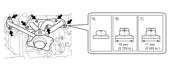
| *A | Type A | *B | Type B |
| *C | Type C | - | - |
Tighten the 7 nuts.
- Torque:
- Type A : 21 N*m (214 kgf*cm, 15 ft.*lbf)
- Type B : 37 N*m (377 kgf*cm, 27 ft.*lbf)
- Type C : 26 N*m (265 kgf*cm, 19 ft.*lbf)
Tighten the 3 bolts.
- Torque:
- 43 N*m (438 kgf*cm, 32 ft.*lbf)
89467B
3.INSTALL AIR FUEL RATIO SENSOR
17167
4.INSTALL NO. 1 EXHAUST MANIFOLD HEAT INSULATOR
Install the No. 1 exhaust manifold heat insulator with the 3 bolts.
- Torque:
- 12 N*m (122 kgf*cm, 9 ft.*lbf)
58151
5.INSTALL FRONT NO. 1 FLOOR HEAT INSULATOR
Install the front No. 1 floor heat insulator with the 3 nuts.
- Torque:
- 5.5 N*m (56 kgf*cm, 49 in.*lbf)
17410
6.INSTALL FRONT EXHAUST PIPE ASSEMBLY (w/ Exhaust Heat Recirculation System)
- NOTICE:
-
When installing the water hose, ensure that the exhaust heat recirculation system is filled with coolant. Otherwise, the engine water pump assembly may be damaged.
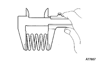
Using a vernier caliper, measure the free length of the compression springs.
| Minimum (front) | 41.5 mm (1.64 in.) |
| Minimum (rear) | 38.5 mm (1.52 in.) |
- HINT:
-
If the free length is less than the minimum, replace the compression spring.
Temporarily install 2 new gaskets to the exhaust manifold and front exhaust pipe assembly.
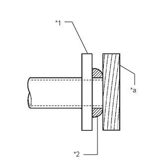
Using a plastic hammer and wooden block, tap in each gasket until its surface is flush with the exhaust manifold and front exhaust pipe assembly.
| *1 | Exhaust Manifold and Front Exhaust Pipe Assembly |
| *2 | Gasket |
| *a | Wooden Block |
- NOTICE:
- ·
Be careful with the installation direction of the gaskets.
·Do not reuse the gaskets.
·Do not damage the gaskets.
·Do not push in the gaskets by using the exhaust pipes when connecting them.
Connect the front exhaust pipe assembly to the 3 exhaust pipe supports.
Install the front exhaust pipe assembly with the 4 bolts and 4 compression springs.
- Torque:
- 43 N*m (438 kgf*cm, 32 ft.*lbf)
Connect the 2 heater water hoses.
Connect the 3 clamps and heated oxygen sensor connector.
17410
7.INSTALL FRONT EXHAUST PIPE ASSEMBLY (w/o Exhaust Heat Recirculation System)
Using a vernier caliper, measure the free length of the compression springs.
| Minimum (front) | 41.5 mm (1.64 in.) |
| Minimum (rear) | 38.5 mm (1.52 in.) |
- HINT:
-
If the free length is less than the minimum, replace the compression spring.
Fully insert 2 new gasket to the exhaust manifold and front exhaust pipe assembly.
Using a plastic hammer and wooden block, tap in each gasket until its surface is flush with the exhaust manifold and front exhaust pipe assembly.
| *1 | Exhaust Manifold and Front Exhaust Pipe Assembly |
| *2 | Gasket |
| *a | Wooden Block |
- NOTICE:
- ·
Be careful with the installation direction of the gasket.
·Do not reuse the gasket.
·Do not damage the gasket.
·Do not push in the gaskets by using the exhaust pipes when connecting them.
Connect the front exhaust pipe assembly to the 3 exhaust pipe supports.
Install the front exhaust pipe assembly with the 4 bolts and 4 compression springs.
- Torque:
- 43 N*m (438 kgf*cm, 32 ft.*lbf)
8.ADD COOLANT (for Engine with Exhaust Heat Recirculation System)
9.INSPECT FOR COOLANT LEAK (for Engine with Exhaust Heat Recirculation System)
57533B
10.INSTALL FRONT CENTER FLOOR BRACE
51442A
11.INSTALL FRONT NO. 3 ENGINE UNDER COVER
51441
12.INSTALL NO. 1 ENGINE UNDER COVER
11212
13.INSTALL NO. 2 CYLINDER HEAD COVER
55701J
14.INSTALL OUTER COWL TOP PANEL SUB-ASSEMBLY (for LHD)
55701J
15.INSTALL OUTER COWL TOP PANEL SUB-ASSEMBLY (for RHD)
55736D
16.INSTALL COWL BODY MOUNTING REINFORCEMENT LH (for LHD)
55735C
17.INSTALL COWL BODY MOUNTING REINFORCEMENT RH (for RHD)
18.INSTALL WINDSHIELD WIPER MOTOR AND LINK ASSEMBLY
19.INSPECT FOR EXHAUST GAS LEAK