BRAKE CONTROL / DYNAMIC CONTROL SYSTEMS ELECTRONICALLY CONTROLLED BRAKE SYSTEM Slip Indicator Light Remains ON
DESCRIPTION
The skid control ECU is connected to the combination meter sub-assembly via CAN communication.
If the skid control ECU stores a DTC, the slip indicator light comes on in the combination meter sub-assembly.
The slip indicator light blinks during VSC and/or TRC operation.
When the system fails, the slip indicator light comes on to warn the driver (See page Brake>BRAKE CONTROL / DYNAMIC CONTROL SYSTEMS>ELECTRONICALLY CONTROLLED BRAKE SYSTEM>DIAGNOSIS SYSTEM).
WIRING DIAGRAM
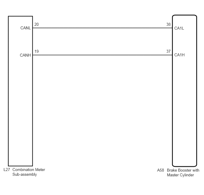
CAUTION / NOTICE / HINT
- NOTICE:
-
When replacing the brake booster with master cylinder (skid control ECU), perform initialization and calibration of the linear solenoid valve (See page Brake>BRAKE CONTROL / DYNAMIC CONTROL SYSTEMS>ELECTRONICALLY CONTROLLED BRAKE SYSTEM>INITIALIZATION).
PROCEDURE
Check if a CAN communication system DTC is output (See page Power Source / Network>NETWORKING>CAN COMMUNICATION SYSTEM (w/o Central Gateway ECU)>DIAGNOSIS SYSTEM).
- Result:
Result Proceed to DTC is not output A DTC is output B
A
B
Check if the skid control ECU connector is securely connected.
- OK:
The connector is securely connected.
OK
NG
Check the auxiliary battery voltage.
- Standard Voltage:
11 to 14 V
OK
NG
Perform the Active Test of the combination meter sub-assembly (meter CPU) using the GTS (See page Vehicle Interior>METER / GAUGE / DISPLAY>METER / GAUGE SYSTEM>DATA LIST / ACTIVE TEST).
Check the combination meter sub-assembly.
- OK:
The slip indicator light turns on or off in accordance with the GTS operation.
- Result:
Result Proceed to OK (for LHD) A OK (for RHD) B NG (w/ Multi-information Display) C NG (w/o Multi-information Display) D
- HINT:
-
If troubleshooting has been carried out according to Problem Symptoms Table, refer back to the table and proceed to the next step before replacing the part (See page Brake>BRAKE CONTROL / DYNAMIC CONTROL SYSTEMS>ELECTRONICALLY CONTROLLED BRAKE SYSTEM>PROBLEM SYMPTOMS TABLE).
A
B
C
D