PRE-CRASH SAFETY PRE-CRASH SAFETY SYSTEM Pre-crash Safety System Cancel Switch Circuit
DESCRIPTION
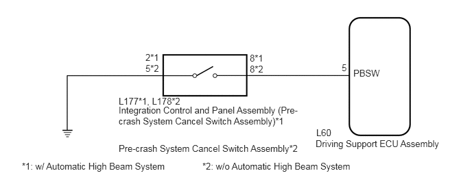
Each time the pre-crash system cancel switch assembly is pressed, the pre-crash system sensitivity indicator on the multi-information display changes and the sensitivity of the pre-crash system is changed in 3 levels. Pressing and holding the pre-crash system cancel switch assembly cancels the pre-crash system.
WIRING DIAGRAM
PROCEDURE
Connect the GTS to the DLC3.
Turn the power switch on (IG).
Turn the GTS on.
Enter the following menus: Body Electrical / Pre-Crash 2 / Data List.
Read the display on the GTS.
| Tester Display | Measurement Item/Range | Normal Condition | Diagnostic Note |
|---|---|---|---|
| Pre-Crash Brake OFF Switch | Pre-crash system cancel switch assembly signal/ON or OFF | ON: Pre-crash system cancel switch assembly on
OFF: Pre-crash system cancel switch assembly off |
- |
- OK:
On screen, each item changes between ON and OFF according to above chart.
OK
NG
Remove the pre-crash system cancel switch assembly (See page Vehicle Interior>PRE-CRASH SAFETY>PRE-CRASH BRAKE CANCEL SWITCH>REMOVAL).
Inspect the the pre-crash system cancel switch assembly (See page Vehicle Interior>PRE-CRASH SAFETY>PRE-CRASH BRAKE CANCEL SWITCH>INSPECTION).
- Result:
Result Proceed to OK A NG (w/ Automatic High Beam System) B NG (w/o Automatic High Beam System) C
A
B
C
Disconnect the L60 driving support ECU assembly connector.
Disconnect the L177*1 or L178*1 pre-crash system cancel switch assembly connector.
*1: w/ Automatic High Beam System
*2: w/o Automatic High Beam System
Measure the resistance according to the value(s) in the table below.
- Standard Resistance:
w/ Automatic High Beam System Tester Connection Condition Specified Condition L177-8 - L60-5 (PBSW) Always Below 1 Ω L177-8 - Body ground Always 10 kΩ or higher L177-2 - Body ground Always Below 1 Ω
w/o Automatic High Beam System Tester Connection Condition Specified Condition L178-8 - L60-5 (PBSW) Always Below 1 Ω L178-8 - Body ground Always 10 kΩ or higher L178-5 - Body ground Always Below 1 Ω
OK
NG