Home › Vehicle Exterior › WINDOW / GLASS › WINDOW DEFOGGER SYSTEM
RM2070E _59 Vehicle Exterior _061949 WINDOW / GLASS _0301874 WINDOW DEFOGGER SYSTEM J

WINDOW / GLASS  WINDOW DEFOGGER SYSTEM  Rear Window Defogger System does not Operate  


DESCRIPTION

When the rear window defogger switch on the air conditioning control assembly is pressed, the operation signal is transmitted to the air conditioning amplifier assembly through a LIN communication line. When the air conditioning amplifier assembly receives the signal, it turns on the No. 1 integration relay to operate the rear window defogger.

WIRING DIAGRAM
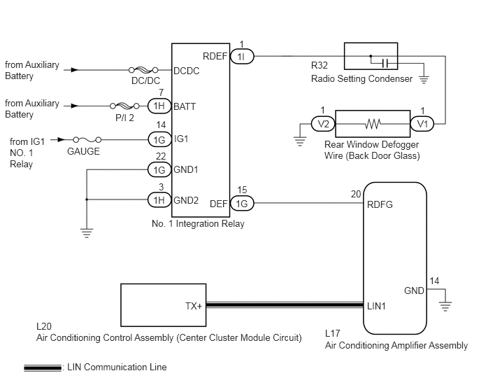
B285913E05
0.927,5.375 2.552,5.521 1.625,0.146 10 false : LIN Communication Line 4.844,5.052 7.073,5.229 2.229,0.177 10 false Air Conditioning Amplifier Assembly 0.542,4.938 4.677,5.104 4.135,0.167 10 false Air Conditioning Control Assembly (Center Cluster Module Circuit) 2.26,3.24 3.75,3.385 1.49,0.146 10 false No. 1 Integration Relay 4.635,1.083 6.25,1.229 1.615,0.146 10 false Radio Setting Condenser 4.833,2.063 6.333,2.385 1.5,0.323 10 false Rear Window Defogger Wire (Back Door Glass) 6.219,1.76 6.406,1.927 0.188,0.167 10 false V1 4.74,1.76 4.948,1.927 0.208,0.167 10 false V2 4.635,0.885 4.927,1.052 0.292,0.167 10 false R32 4.771,1.552 4.896,1.708 0.125,0.156 10 false 1 6.26,1.563 6.385,1.719 0.125,0.156 10 false 1 3.563,0.573 3.688,0.729 0.125,0.156 10 false 1 3.531,0.76 3.688,0.917 0.156,0.156 10 false 1I 3.51,2.948 3.719,3.104 0.208,0.156 10 false 1G 3.531,2.74 3.719,2.896 0.188,0.156 10 false 15 1.958,1.115 2.417,1.26 0.458,0.146 10 false DC/DC 0.073,0.875 0.958,1.188 0.885,0.313 10 false from Auxiliary Battery 0.073,1.448 0.958,1.76 0.885,0.313 10 false from Auxiliary Battery 0.146,2.021 0.719,2.531 0.573,0.51 10 false from IG1 NO. 1 Relay 5.469,4.469 5.781,4.615 0.313,0.146 10 false LIN1 2.76,4.469 3.042,4.615 0.281,0.146 10 false TX+ 5.469,2.958 5.938,3.104 0.469,0.146 10 false RDFG 5.229,2.802 5.458,2.99 0.229,0.188 10 false 20 4.844,4.875 5.125,5.042 0.281,0.167 10 false L17 0.542,4.771 0.833,4.938 0.292,0.167 10 false L20 6.021,4.24 6.354,4.385 0.333,0.146 10 false GND 6.396,4.094 6.583,4.25 0.188,0.156 10 false 14 3.125,2.948 3.427,3.104 0.302,0.156 10 false DEF 3.021,0.75 3.427,0.906 0.406,0.156 10 false RDEF 2.583,0.969 3.01,1.125 0.427,0.156 10 false DCDC 2.583,1.5 3.01,1.656 0.427,0.156 10 false BATT 2.594,1.979 2.854,2.135 0.26,0.156 10 false IG1 2.583,2.438 3.01,2.594 0.427,0.156 10 false GND1 2.583,2.896 3.01,3.052 0.427,0.156 10 false GND2 1.719,1.667 2.031,1.813 0.313,0.146 10 false P/I 2 2.281,1.49 2.49,1.646 0.208,0.156 10 false 1H 2.281,2.896 2.49,3.052 0.208,0.156 10 false 1H 2.365,1.292 2.49,1.448 0.125,0.156 10 false 7 2.365,2.698 2.49,2.854 0.125,0.156 10 false 3 2.323,2.24 2.5,2.396 0.177,0.156 10 false 22 2.323,1.771 2.5,1.927 0.177,0.156 10 false 14 2.281,2.448 2.49,2.604 0.208,0.156 10 false 1G 2.281,2 2.49,2.156 0.208,0.156 10 false 1G 1,2.167 1.563,2.313 0.563,0.146 10 false GAUGE

CAUTION / NOTICE / HINT

NOTICE:
·

Inspect the fuses for circuits related to this system before performing the following inspection procedure.

·

If the auxiliary battery voltage becomes low, rear window defogger operation is canceled to prioritize supplying power to the power steering system.


PROCEDURE

1.CHECK AIR CONDITIONING SYSTEM
a.

Check the air conditioning system.

HINT:

Both the window defogger system operation signal and air conditioning system operation signal are transmitted to the air conditioning amplifier assembly through the same communication line.


OK:

The air conditioning system operates normally.


OK

2.PERFORM ACTIVE TEST USING GTS (DEFOGGER RELAY)

NG

2.PERFORM ACTIVE TEST USING GTS (DEFOGGER RELAY)
a.

Connect the GTS to the DLC3.


b.

Turn the power switch on (IG).


c.

Turn the GTS on.


d.

Enter the following menus: Body Electrical / Air Conditioner / Active Test.


e.

Perform the Active Test according to the display on the GTS.

Air Conditioner
Tester Display Test Part Control Range Diagnostic Note
Defogger Relay (Rear) Rear window defogger OFF or ON Operate with power switch on (IG)

OK:

The rear window defogger system operates normally.


OK

3.REPLACE AIR CONDITIONING AMPLIFIER ASSEMBLY

NG

4.CHECK HARNESS AND CONNECTOR (NO. 1 INTEGRATION RELAY - AUXILIARY BATTERY AND BODY GROUND)
3.REPLACE AIR CONDITIONING AMPLIFIER ASSEMBLY
a.

Temporarily replace the air conditioning amplifier assembly with a new or known good one (See page Vehicle Interior>HEATING / AIR CONDITIONING>AIR CONDITIONING AMPLIFIER>REMOVAL).


b.

Check that the rear window defogger system operates normally.

OK:

The rear window defogger system operates normally.


OK

END (AIR CONDITIONING AMPLIFIER ASSEMBLY WAS DEFECTIVE)

NG

REPLACE AIR CONDITIONING CONTROL ASSEMBLY (CENTER CLUSTER MODULE CIRCUIT)

4.CHECK HARNESS AND CONNECTOR (NO. 1 INTEGRATION RELAY - AUXILIARY BATTERY AND BODY GROUND)
a.

Disconnect the 1G and 1H No. 1 integration relay connectors.


b.

Measure the voltage and resistance according to the value(s) in the table below.

Standard Voltage:
Tester Connection Condition Specified Condition
1H-7 (BATT) - Body ground Power switch off 11 to 14 V
1G-14 (IG1) - Body ground Power switch on (IG) 11 to 14 V
1G-14 (IG1) - Body ground Power switch off Below 1 V


Standard Resistance:
Tester Connection Condition Specified Condition
1G-22 (GND1) - Body ground Always Below 1 Ω
1H-3 (GND2) - Body ground Always Below 1 Ω


OK

5.CHECK HARNESS AND CONNECTOR (AIR CONDITIONING AMPLIFIER - NO. 1 INTEGRATION RELAY)

NG

REPAIR OR REPLACE HARNESS OR CONNECTOR

5.CHECK HARNESS AND CONNECTOR (AIR CONDITIONING AMPLIFIER - NO. 1 INTEGRATION RELAY)
a.

Disconnect the L17 air conditioning amplifier assembly connector.


b.

Measure the resistance according to the value(s) in the table below.

Standard Resistance:
Tester Connection Condition Specified Condition
L17-20 (RDFG) - 1G-15 (DEF) Always Below 1 Ω
1G-15 (DEF) - Body ground Always 10 kΩ or higher
L17-14 (GND) - Body ground Always Below 1 Ω


OK

6.CHECK NO. 1 INTEGRATION RELAY

NG

REPAIR OR REPLACE HARNESS OR CONNECTOR

6.CHECK NO. 1 INTEGRATION RELAY
a.

Reconnect the 1G and 1H No. 1 integration relay connectors.


b.

Measure the voltage according to the value(s) in the table below.

Standard Voltage:
Tester Connection Condition Specified Condition
L17-20 (RDFG) - Body ground Power switch on (IG) 11 to 14 V


OK

7.CHECK AIR CONDITIONING AMPLIFIER ASSEMBLY

NG

7.CHECK AIR CONDITIONING AMPLIFIER ASSEMBLY
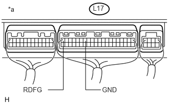
a.
U154536E01
0.163,0.104 0.346,0.273 0.184,0.170 10 *a 2.075,1.753 2.404,1.904 0.330,0.151 10 GND 1.889,0.084 2.173,0.228 0.284,0.144 10 L17 0.47,1.753 0.884,1.904 0.414,0.151 10 RDFG 1.287,0.836 1.287,1.835 1.287,1.835 0.975,1.835 false 1.74,0.836 1.74,1.835 1.74,1.835 2.052,1.835 false

Reconnect the L17 air conditioning amplifier assembly connector.


b.

Measure the voltage according to the value(s) in the table below.

Standard Voltage:
Tester Connection Condition Specified Condition
L17-20 (RDFG) - L17-14 (GND) Power switch on (IG), rear window defogger switch off 11 to 14 V
L17-20 (RDFG) - L17-14 (GND) Power switch on (IG), rear window defogger switch on Below 2 V


Text in Illustration
*a Component with harness connected
(to Air Conditioning Amplifier Assembly)


OK

8.CHECK HARNESS AND CONNECTOR (NO. 1 INTEGRATION RELAY - REAR WINDOW DEFOGGER WIRE)

NG

REPLACE AIR CONDITIONING AMPLIFIER ASSEMBLY

8.CHECK HARNESS AND CONNECTOR (NO. 1 INTEGRATION RELAY - REAR WINDOW DEFOGGER WIRE)
a.

Disconnect the V1 rear window defogger wire (back door glass) auxiliary battery side connector.


b.

Disconnect the 1I No. 1 integration relay connector.


c.

Measure the resistance according to the value(s) in the table below.

Standard Resistance:
Tester Connection Condition Specified Condition
1I-1 (RDEF) - Body ground Always 10 kΩ or higher
1I-1 (RDEF) - V1-1 Always Below 1 Ω


OK

9.CHECK NO. 1 INTEGRATION RELAY

NG

REPAIR OR REPLACE HARNESS OR CONNECTOR

9.CHECK NO. 1 INTEGRATION RELAY
a.

Reconnect the 1I No. 1 integration relay connector.


b.

Measure the voltage according to the value(s) in the table below.

Standard Voltage:
Tester Connection Condition Specified Condition
V1-1 - Body ground Power switch on (IG), rear window defogger switch on 11 to 14 V
V1-1 - Body ground Power switch on (IG), rear window defogger switch off Below 1 V


OK

10.CHECK HARNESS AND CONNECTOR (REAR WINDOW DEFOGGER WIRE - BODY GROUND)

NG

11.REPLACE NO. 1 INTEGRATION RELAY
10.CHECK HARNESS AND CONNECTOR (REAR WINDOW DEFOGGER WIRE - BODY GROUND)
a.

Disconnect the V2 rear window defogger wire (back door glass) ground side connector.


b.

Measure the resistance according to the value(s) in the table below.

Standard Resistance:
Tester Connection Condition Specified Condition
V2-1 - Body ground Always Below 1 Ω


OK

REPAIR OR REPLACE REAR WINDOW DEFOGGER WIRE (BACK DOOR GLASS)

NG

REPAIR OR REPLACE HARNESS OR CONNECTOR

11.REPLACE NO. 1 INTEGRATION RELAY
a.

Replace the No. 1 integration relay (See page Power Source / Network>POWER DISTRIBUTION>INTEGRATION RELAY>REMOVAL).


NEXT

12.CHECK WINDOW DEFOGGER SYSTEM
a.

Check the operation of the window defogger system.

OK:

The rear window defogger system operates normally.


OK

END (NO. 1 INTEGRATION RELAY WAS DEFECTIVE)

NG

REPAIR OR REPLACE HARNESS OR CONNECTOR (POWER SOURCE)