METER / GAUGE / DISPLAY METER / GAUGE SYSTEM Steering Pad Switch Circuit
DESCRIPTION
The combination meter sub-assembly and steering pad switch RH are connected via direct line. The multi-information display is operated using the switches of the steering pad switch RH.
WIRING DIAGRAM
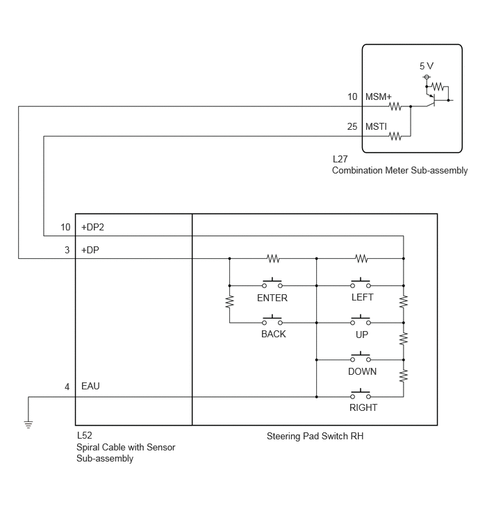
PROCEDURE
Connect the GTS to the DLC3.
Turn the power switch on (IG).
Turn the GTS on.
Enter the following menus: Body Electrical / Combination Meter / Data List.
Read the Data List according to the display on the GTS.
| Tester Display | Measurement Item/Range | Normal Condition | Diagnostic Note |
|---|---|---|---|
| Multi Switch (Up) | Up switch / OFF or ON | OFF: Up switch on steering pad switch not pushed | - |
| ON: Up switch on steering pad switch pushed | |||
| Multi Switch (Down) | Down switch / OFF or ON | OFF: Down switch on steering pad switch not pushed | - |
| ON: Down switch on steering pad switch pushed | |||
| Multi Switch (Enter) | Enter switch / OFF or ON | OFF: Enter switch on steering pad switch not pushed | - |
| ON: Enter switch on steering pad switch pushed | |||
| Multi Switch (Right) | Right switch / OFF or ON | OFF: Right switch on steering pad switch not pushed | - |
| ON: Right switch on steering pad switch pushed | |||
| Multi Switch (Left) | Left switch / OFF or ON | OFF: Left switch on steering pad switch not pushed | - |
| ON: Left switch on steering pad switch pushed | |||
| Multi Switch (Back) | Back switch / OFF or ON | OFF: Back switch on steering pad switch not pushed | - |
| ON: Back switch on steering pad switch pushed |
- Result:
Result Proceed to The Data List item changes correctly A The Data List item do not change correctly B
A
B
Remove the steering pad switch RH.
Click hereSteering>STEERING COLUMN>STEERING PAD SWITCH>REMOVAL
Inspect the steering pad switch RH.
Click hereSteering>STEERING COLUMN>STEERING PAD SWITCH>INSPECTION
- Result:
Proceed to OK NG
OK
NG
Remove the spiral cable with sensor sub-assembly.
Click hereVehicle Interior>SUPPLEMENTAL RESTRAINT SYSTEMS>SPIRAL CABLE>REMOVAL
Inspect the spiral cable with sensor sub-assembly.
Click hereVehicle Interior>SUPPLEMENTAL RESTRAINT SYSTEMS>SPIRAL CABLE>INSPECTION
- Result:
Proceed to OK NG
OK
NG
Disconnect the L27 combination meter sub-assembly connector.
Measure the resistance according to the value(s) in the table below.
- Standard Resistance:
Tester Connection Condition Specified Condition L52-3 (+DP) - L27-10 (MSM+) Always Below 1 Ω L52-10 (+DP2) - L27-25 (MSTI) Always Below 1 Ω L52-3 (+DP) or L27-10 (MSM+) - Body ground Always 10 kΩ or higher L52-10 (+DP2) or L27-25 (MSTI) - Body ground Always 10 kΩ or higher L52-4 (EAU) - Body ground Always Below 1 Ω
- Result:
Proceed to OK NG
OK
NG