Home › Brake › BRAKE CONTROL / DYNAMIC CONTROL SYSTEMS › REAR SPEED SENSOR

REAR SPEED SENSOR > INSTALLATION

for Preparation Click here


HINT:
  1. Use the same procedure for the LH side and RH side.
  2. The following procedure is for the LH side.
  3. If the sensor rotor needs to be replaced, replace the rear axle hub and bearing assembly.
  4. The rear speed sensor is a component of the rear axle hub and bearing assembly. If the rear speed sensor malfunctions, replace the rear axle hub and bearing assembly.


1. INSTALL REAR AXLE HUB AND BEARING ASSEMBLY
  1. Install the rear axle hub and bearing assembly .

    HINT:
    1. The rear speed sensor is a component of the rear axle hub and bearing assembly. If the sensor malfunctions, replace the rear axle hub and bearing assembly.
    2. If the sensor rotor needs to be replaced, replace the rear axle hub and bearing assembly.


2. INSPECT REAR AXLE HUB BEARING LOOSENESS


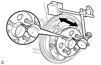
    C249956
  1. Using a dial indicator, check for looseness near the center of the rear axle hub.

    Maximum looseness:
    0.05 mm (0.00196 in.)

    NOTICE:
    1. Ensure that the dial indicator is set perpendicular to the measurement surface.
    2. Keep the magnet of the dial indicator away from the rear axle hub and bearing assembly (rear speed sensor).
    If the looseness exceeds the maximum, replace the rear axle hub and bearing assembly.


3. INSPECT REAR AXLE HUB RUNOUT


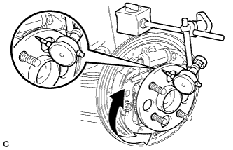
    C249957
  1. Using a dial indicator, check for runout on the surface of the axle hub outside the rear axle hub bolts.

    Maximum runout:
    0.07 mm (0.00276 in.)

    NOTICE:
    1. Ensure that the dial indicator is set perpendicular to the measurement surface.
    2. Make sure to set the tip of the dial indicator towards the outside of the rear axle hub bolts.
    3. Keep the magnet of the dial indicator away from the rear axle hub and bearing assembly (rear speed sensor).
    If the runout exceeds the maximum, replace the rear axle hub and bearing assembly.


4. INSTALL REAR BRAKE DRUM SUB-ASSEMBLY
  1. Install the rear brake drum sub-assembly.


5. CONNECT SKID CONTROL SENSOR WIRE


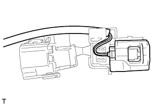
    C235058
  1. Install the skid control sensor wire connector to the connector cover.


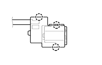
    C235580
  1. Engage the 3 claws to secure the connector cover.

  1. Connect the skid control sensor wire connector to the rear axle hub and bearing assembly.


6. INSTALL REAR WHEEL

Torque:
103 N*m{ 1050 kgf*cm , 76 ft.*lbf }


7. CONNECT CABLE TO AUXILIARY BATTERY NEGATIVE TERMINAL
  1. Connect the cable to the negative (-) auxiliary battery terminal .

  1. Connect the reservoir level switch connector.

  1. Clear the DTCs (Click here).


8. INSPECT REAR WHEEL ALIGNMENT
(Click here)


9. CHECK FOR SPEED SENSOR SIGNAL
(Click here)