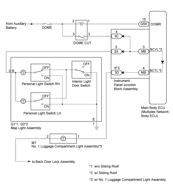
LIGHTING SYSTEM > Interior Light Power Source Circuit |
| 1.INSPECT DOME CUT RELAY |
Remove the DOME CUT relay from the No. 2 engine room relay block and No. 2 junction block assembly.
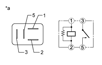 |
Measure the resistance according to the value(s) in the table below.
| Tester Connection | Condition | Specified Condition |
| 3 - 5 | Voltage is not applied between terminals 1 and 2 | 10 kΩ or higher |
| 3 - 5 | Voltage is applied between terminals 1 and 2 | Below 1 Ω |
| *a | Component without harness connected (DOME CUT Relay) |
|
| ||||
| OK | |
 |
| 2.CHECK HARNESS AND CONNECTOR (AUXILIARY BATTERY - DOME CUT RELAY) |
Measure the voltage according to the value(s) in the table below.
| Tester Connection | Switch Condition | Specified Condition |
| Relay Terminal 2 - Body ground | Ignition switch off | 11 to 14 V |
| Relay Terminal 5 - Body ground | Ignition switch off | 11 to 14 V |
|
| ||||
| OK | |
|
| 3.CHECK HARNESS AND CONNECTOR (DOME CUT RELAY - INSTRUMENT PANEL JUNCTION BLOCK ASSEMBLY) |
Disconnect the 3C instrument panel junction block assembly connector.
Measure the resistance according to the value(s) in the table below.
| Tester Connection | Switch Condition | Specified Condition |
| Relay Terminal 3 - 3C-4 | Always | Below 1 Ω |
| Relay Terminal 3 - Body ground | Always | 10 kΩ or higher |
|
| ||||
| OK | |
|
| 4.CHECK HARNESS AND CONNECTOR (DOME CUT RELAY - MAIN BODY ECU (MULTIPLEX NETWORK BODY ECU)) |
Disconnect the G59 main body ECU (multiplex network body ECU) connector.
Measure the resistance according to the value(s) in the table below.
| Tester Connection | Switch Condition | Specified Condition |
| Relay Terminal 1 - G59-15 (DOMR) | Always | Below 1 Ω |
| Relay Terminal 1 - Body ground | Always | 10 kΩ or higher |
| Result | Proceed to |
| OK (w/o Luggage Compartment Light) | A |
| OK (w/ Luggage Compartment Light) | B |
| NG | C |
|
| ||||
|
| ||||
| A | |
|
| 5.INSPECT INSTRUMENT PANEL JUNCTION BLOCK ASSEMBLY |
Remove the instrument panel junction block assembly (Click here).
Remove the main body ECU (multiplex network body ECU) from the instrument panel junction block assembly.
Measure the resistance according to the value(s) in the table below.
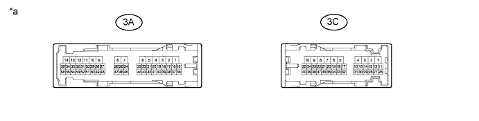
| *a | Component without harness connected (Instrument Panel Junction Block Assembly) | - | - |
| Tester Connection | Switch Condition | Specified Condition |
| 3C-4 - 3A-5 | Always | Below 1 Ω |
|
| ||||
| OK | |
|
| 6.INSPECT MAP LIGHT ASSEMBLY |
Remove the map light assembly (Click here).
Inspect the map light assembly (Click here).
|
| ||||
| OK | |
|
| 7.CHECK HARNESS AND CONNECTOR (MAP LIGHT ASSEMBLY - INSTRUMENT PANEL JUNCTION BLOCK ASSEMBLY AND BODY GROUND) |
Disconnect the 3A instrument panel junction block assembly connector.
Measure the resistance according to the value(s) in the table below.
| Tester Connection | Switch Condition | Specified Condition |
| Q1-3 (B) - 3A-5*1 | Always | Below 1 Ω |
| Q1-3 (B) - Body ground*1 | Always | 10 kΩ or higher |
| Q1-1 (E) - Body ground*1 | Always | Below 1 Ω |
| Q2-3 (B) - 3A-5*2 | Always | Below 1 Ω |
| Q2-3 (B) - Body ground*2 | Always | 10 kΩ or higher |
| Q2-1 (E) - Body ground*2 | Always | Below 1 Ω |
|
| ||||
| OK | ||
 | ||
| ||
| 8.INSPECT INSTRUMENT PANEL JUNCTION BLOCK ASSEMBLY |
Remove the instrument panel junction block assembly (Click here).
Remove the main body ECU (multiplex network body ECU) from the instrument panel junction block assembly.
Measure the resistance according to the value(s) in the table below.
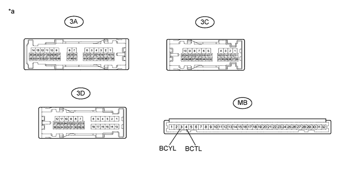
| *a | Component without harness connected (Instrument Panel Junction Block Assembly) | - | - |
| Tester Connection | Switch Condition | Specified Condition |
| 3C-4 - MB-3 (BCYL) | Always | Below 1 Ω |
| 3A-5 - MB-3 (BCYL) | Always | Below 1 Ω |
| 3D-6 - MB-4 (BCTL) | Always | Below 1 Ω |
|
| ||||
| OK | ||
| ||
| ||

