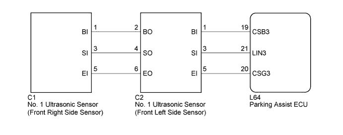
DTC C1AEE IPA Sensor Communication Circuit |
| DTC No. | DTC Detection Condition | Trouble Area |
| C1AEE | Ultrasonic sensor communication bus failure |
|
| 1.CHECK HARNESS AND CONNECTOR (PARKING ASSIST ECU - FRONT LEFT SIDE SENSOR) |
Disconnect the L64 connector from the parking assist ECU.
Disconnect the C2 connector from the No. 1 ultrasonic sensor (front left side sensor).
Measure the resistance according to the value(s) in the table below.
| Tester Connection | Condition | Specified Condition |
| L64-19 (CSB3) - Body ground | Always | 10 kΩ or higher |
| L64-21 (LIN3) - Body ground | Always | 10 kΩ or higher |
| L64-20 (CSG3) - Body ground | Always | 10 kΩ or higher |
| L64-19 (CSB3) - C2-1 (BI) | Always | Below 1 Ω |
| L64-21 (LIN3) - C2-3 (SI) | Always | Below 1 Ω |
| L64-20 (CSG3) - C2-5 (EI) | Always | Below 1 Ω |
|
| ||||
| OK | |
 |
| 2.CHECK NO. 1 ULTRASONIC SENSOR |
Remove the No. 1 ultrasonic sensor (front left side sensor) (Click here).
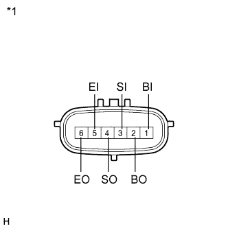 |
Measure the resistance according to the value(s) in the table below.
| Tester Connection | Condition | Specified Condition |
| 1 (BI) - 5 (EI) | Always | 10 kΩ or higher |
| 1 (BI) - 2 (BO) | Always | 10 kΩ or higher |
| 3 (SI) - 4 (SO) | Always | Below 1 Ω |
| 5 (EI) - 6 (EO) | Always | Below 1 Ω |
| *1 | Component without harness connected (No. 1 Ultrasonic Sensor (Front Left Side Sensor)) |
|
| ||||
| OK | |
|
| 3.CHECK HARNESS AND CONNECTOR (FRONT LEFT SIDE SENSOR - FRONT RIGHT SIDE SENSOR) |
Disconnect the C2 connector from the No. 1 ultrasonic sensor (front left side sensor).
Disconnect the C1 connector from the No. 1 ultrasonic sensor (front right side sensor).
Measure the resistance according to the value(s) in the table below.
| Tester Connection | Condition | Specified Condition |
| C2-2 (BO) - C1-1 (BI) | Always | Below 1 Ω |
| C2-4 (SO) - C1-3 (SI) | Always | Below 1 Ω |
| C2-6 (EO) - C1-5 (EI) | Always | Below 1 Ω |
| C2-2 (BO) - Body ground | Always | 10 kΩ or higher |
| C2-4 (SO) - Body ground | Always | 10 kΩ or higher |
| C2-6 (EO) - Body ground | Always | 10 kΩ or higher |
|
| ||||
| OK | |
|
| 4.REPLACE NO. 1 ULTRASONIC SENSOR (FRONT LEFT SIDE SENSOR) |
Replace the No. 1 ultrasonic sensor (front left side sensor) with a normally functioning sensor (Click here).
| NEXT | |
|
| 5.CHECK DTC OUTPUT |
Clear the DTCs (Click here).
Check for DTCs (Click here).
| Result | Proceed to |
| DTC C1AEE is output | A |
| No DTC is output | B |
|
| ||||
| A | |
|
| 6.REPLACE NO. 1 ULTRASONIC SENSOR (FRONT RIGHT SIDE SENSOR) |
Replace the No. 1 ultrasonic sensor (front right side sensor) with a normally functioning sensor (Click here).
| NEXT | |
|
| 7.CHECK DTC OUTPUT |
Clear the DTCs (Click here).
Check for DTCs (Click here).
| Result | Proceed to |
| DTC C1AEE is output | A |
| No DTC is output | B |
|
| ||||
| A | ||
 | ||
| ||
