| NEXT | |
 |
CAN COMMUNICATION SYSTEM > HOW TO PROCEED WITH TROUBLESHOOTING |
| 1.VEHICLE BROUGHT TO WORKSHOP |
| |||||
| 2.CUSTOMER PROBLEM ANALYSIS |
Interview the customer and confirm the problem.
| |||||
| 3.CHECK AUXILIARY BATTERY |
| |||||
| 4.CHECK AND CLEAR DTCS* |
| |||||
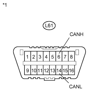
| 5.CHECK FOR DLC3 BRANCH WIRE AND CAN NO. 1 BUS MAIN WIRE (CANH - CANL) |
 |
Turn the power switch off.
Measure the resistance according to the value(s) in the table below.
| Tester Connection | Switch Condition | Specified Condition |
| L61-6 (CANH) - L61-14 (CANL) | Power switch off | 54 to 69 Ω |
| *1 | DLC3 |
| Result | Proceed to |
| OK | A |
| NG (70 Ω or higher) | B |
| NG (Below 54 Ω) | C |
|
| ||||
|
| ||||
| |||||
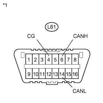
| 6.CHECK FOR SHORT TO GND IN CAN NO. 1 BUS (CANH, CANL - CG) |
 |
Turn the power switch off.
Measure the resistance according to the value(s) in the table below.
| Tester Connection | Switch Condition | Specified Condition |
| L61-6 (CANH) - L61-4 (CG) | Power switch off | 200 Ω or higher |
| L61-14 (CANL) - L61-4 (CG) | Power switch off | 200 Ω or higher |
| *1 | DLC3 |
|
| ||||
| |||||
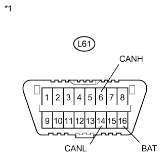
| 7.CHECK FOR SHORT TO +B IN CAN NO. 1 BUS (CANH, CANL - BAT) |
 |
Disconnect the cable from the negative (-) auxiliary battery terminal.
Measure the resistance according to the value(s) in the table below.
| Tester Connection | Condition | Specified Condition |
| L61-6 (CANH) - L61-16 (BAT) | Cable disconnected from negative (-) auxiliary battery terminal | 6 kΩ or higher |
| L61-14 (CANL) - L61-16 (BAT) | Cable disconnected from negative (-) auxiliary battery terminal | 6 kΩ or higher |
| *1 | DLC3 |
|
| ||||
| |||||
| 8.CHECK INSTALLED SYSTEMS (ECU AND SENSOR) THAT USE CAN COMMUNICATION |
Based on the vehicle equipment and specifications, confirm the systems that use CAN communication (Click here).
| |||||
| 9.CHECK ECUS CONNECTED TO CAN BUS* |
Select "CAN Bus Check" from the screen on the Techstream (Click here).
Observe the screen for approximately 1 minute to check the ECUs and sensors displayed on the screen.
| Result | Proceed to |
| All ECUs and sensors connected to the CAN communication system are displayed on the screen. (CAN bus circuit is currently normal.) | A |
| B |
| C |
| The driving support ECU (Pre-Collision2) outputs DTC U1002. (Open or short in parking assist bus main wires.) | D |
| All ECUs connected to the CAN No. 2 bus and power management bus are not displayed on the screen. (Open in power management control ECU branch wires or power management control ECU malfunction.) | E |
| One of the ECUs and sensors connected to the CAN No. 1 bus is not displayed on the screen. (Open in ECU or sensor branch wires, or communication interrupted.) | F |
| One of the ECUs and sensors connected to the CAN No. 2 bus or power management bus is not displayed on the screen. (Open in ECU or sensor branch wires, or communication interrupted.) | G |
| Some ECUs and sensors repeatedly appear and disappear on the screen during this check. (Open in one side of ECU or sensor branch wires.) | H |
|
| ||||
|
| ||||
|
| ||||
|
| ||||
|
| ||||
|
| ||||
|
| ||||
| |||||
| 10.RECHECK DTC |
| Result | Proceed to |
| Communication error DTCs other than the codes output from the power management control ECU are output. (A malfunction occurred in the CAN No. 1 bus.) | A |
| The power management control ECU (Power Management1) outputs DTC 1002. (A malfunction occurred in the CAN No. 2 bus.) | B |
| The power management control ECU (Power Management2) outputs DTC 1002. (A malfunction occurred in the power management bus.) | C |
| The driving support ECU (Pre-Collision2) outputs DTC 1002. (A malfunction occurred in the parking assist bus.) | D |
| The power management ECU outputs DTCs other than DTC 1002. (A malfunction occurred in an ECU branch wire connected to the CAN No. 2 bus or power management bus.) | E |
|
| ||||
|
| ||||
|
| ||||
|
| ||||
| |||||
| 11.DTC COMBINATION TABLE |
Confirm trouble according to the combination of output DTCs regarding the CAN communication system (Click here).
| |||||
| 12.CIRCUIT INSPECTION |
| |||||
| 13.IDENTIFICATION OF PROBLEM |
| |||||
| 14.REPAIR OR REPLACEMENT |
| |||||
| 15.CONFIRMATION TEST* |
|
| ||||
|---|---|---|---|---|---|
