 |
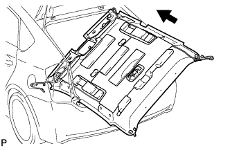
Put the roof headlining assembly into the vehicle through the back door.
- NOTICE:
- Do not damage the roof headlining assembly or body interior.
ROOF HEADLINING > INSTALLATION |
| 1. INSTALL ROOF HEADLINING ASSEMBLY (w/o Sliding Roof) |
|
Put the roof headlining assembly into the vehicle through the back door.
Install the 5 clips.
Connect the 2 connectors to the connector holder.
Engage the 4 clamps to the front pillar LH.
w/o Manual (SOS) Switch:
Engage the 3 clamps and connect the connector to the front pillar RH.
Disengage the clamp and disconnect the connector to the rear pillar RH.
w/ Manual (SOS) Switch:
Engage the 3 clamps and connect the 2 connectors to the front pillar RH.
Engage the clamp and connect the 2 connectors to the rear pillar RH.
w/ EC Mirror:
Connect the inner rear view mirror connector and engage the 2 clamps.
w/ Lane Keeping Assist System:
Connect the inner rear view mirror connector and engage the clamp.
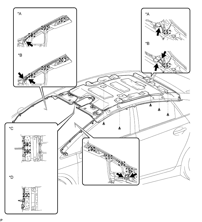
| *A | w/o Manual (SOS) Switch | *B | w/ Manual (SOS) Switch |
| *C | w/ EC Mirror | *D | w/ Lane Keeping Assist System |
| 2. INSTALL ROOF HEADLINING ASSEMBLY (w/ Sliding Roof) |
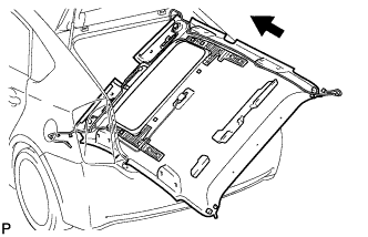 |
Put the roof headlining assembly into the vehicle through the back door.
Engage the 6 fasteners.
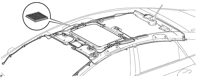
Install the 3 clips.
Connect the 2 connectors to the connector holder.
Engage the 4 clamps to the front pillar LH.
w/o Manual (SOS) Switch:
Engage the 3 clamps and connect the connector to the front pillar RH.
Disengage the clamp and disconnect the connector to the rear pillar RH.
w/ Manual (SOS) Switch:
Engage the 3 clamps and connect the 2 connectors to the front pillar RH.
Engage the clamp and connect the 2 connectors to the rear pillar RH.
w/ EC Mirror:
Connect the inner rear view mirror connector and engage the 2 clamps.
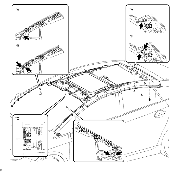
| *A | w/o Manual (SOS) Switch | *B | w/ Manual (SOS) Switch |
| *C | w/ EC Mirror | - | - |
| 3. INSTALL VISOR HOLDER |
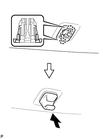 |
Engage the 2 claws.
Push in the visor holder as shown in the illustration.
| 4. INSTALL VISOR ASSEMBLY LH |
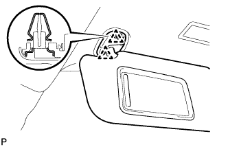 |
Engage the 2 clips to install the visor assembly LH.
| 5. INSTALL VISOR BRACKET COVER LH |
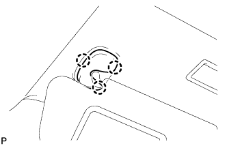 |
Engage the 3 claws to install the visor bracket cover LH.
| 6. INSTALL VISOR ASSEMBLY RH |
| 7. INSTALL VISOR BRACKET COVER RH |
| 8. INSTALL FRONT ASSIST GRIP ASSEMBLY |
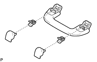 |
Assemble the front assist grip assembly as shown in the illustration.
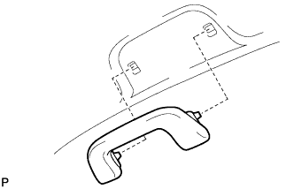 |
Install the front assist grip assembly.
| 9. INSTALL REAR ASSIST GRIP ASSEMBLY |
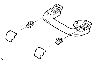 |
Assemble the rear assist grip assembly as shown in the illustration.
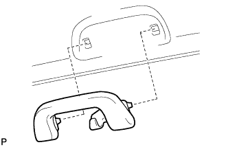 |
Install the rear assist grip assembly.
| 10. INSTALL NO. 1 ROOM LIGHT ASSEMBLY |
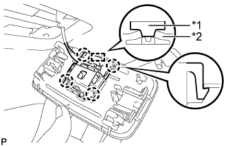 |
Align the switch parts shown in the illustration and engage the 4 claws to install the room light switch base to the No. 1 room light assembly.
| *1 | Switch Part of Room Light Switch Base |
| *2 | Switch Part of No. 1 Room Light Assembly |
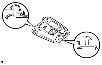 |
Engage the 4 claws and install the No. 1 room light assembly.
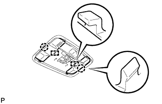 |
Engage the 2 claws and 2 guides to install the 2 No. 1 room light covers.
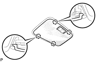 |
Engage the 4 claws to install the No. 1 room light lens.
| 11. INSTALL MAP LIGHT ASSEMBLY (w/o Sliding Roof) |
Connect the connector.
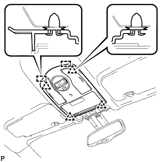 |
Engage the 2 guides and 4 clips, and install the map light assembly.
| 12. INSTALL MAP LIGHT ASSEMBLY (w/ Sliding Roof) |
Connect the connector.
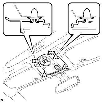 |
Engage the 2 guides and 4 clips, and install the map light assembly.
| 13. INSTALL LANE RECOGNITION CAMERA SENSOR ASSEMBLY (w/ Lane Keeping Assist System) |
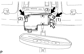 |
Attach the lane recognition camera sensor assembly with the clip.
Temporarily install the lane recognition camera sensor assembly with the 3 bolts.
Tighten the 3 bolts in the order shown in the illustration to install the lane recognition camera sensor assembly.
Connect the connector.
| 14. INSTALL ROOF TOP MOULDING (w/o Lane Keeping Assist System) |
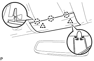 |
Engage the 3 claws and 2 clips to install the roof top moulding.
| 15. INSTALL ROOF TOP MOULDING (w/ Lane Keeping Assist System) |
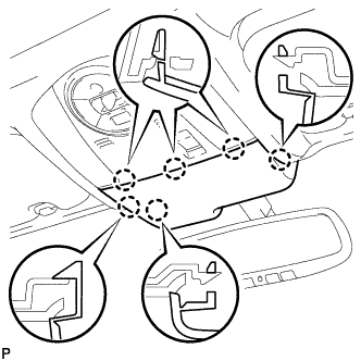 |
Engage the 6 claws to install the roof top moulding.
| 16. INSTALL INNER REAR VIEW MIRROR COVER (w/ EC Mirror) |
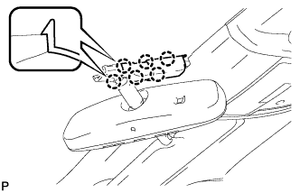 |
Engage the 6 claws and install the inner rear view mirror cover.
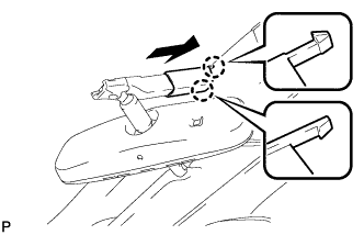 |
Engage the 2 claws and install the inner rear view mirror cover as shown in the illustration.
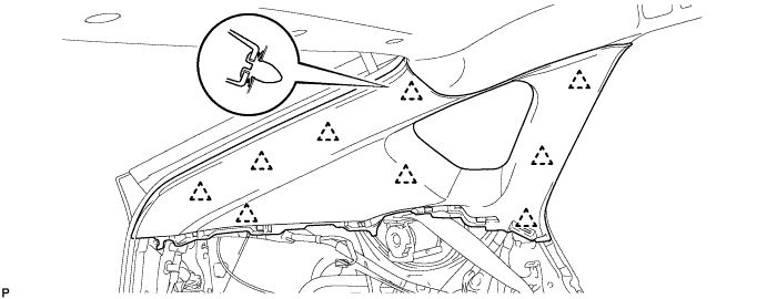
| 17. INSTALL ROOF SIDE INNER GARNISH ASSEMBLY LH |
Engage the 9 clips to install the roof side inner garnish assembly LH.
| 18. INSTALL DECK TRIM SIDE PANEL ASSEMBLY LH |
Connect the connector.
Engage the 7 claws and 2 clips.
Install the deck trim side panel assembly LH with the screw.
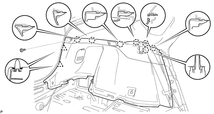
| 19. INSTALL TONNEAU COVER HOLDER CAP (for LH Side) |
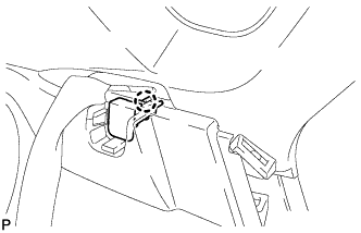 |
Engage the claw to install the tonneau cover holder cap.
| 20. INSTALL LUGGAGE HOLD BELT STRIKER ASSEMBLY (for LH Side) |
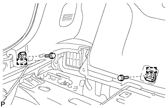 |
Engage the 2 guides.
Install the 2 luggage hold belt striker assemblies with the 2 bolts.
| 21. INSTALL ROOF SIDE INNER GARNISH ASSEMBLY RH |
| 22. INSTALL DECK TRIM SIDE PANEL ASSEMBLY RH |
Engage the 7 claws and 2 clips.
Install the deck trim side panel assembly RH with the screw.
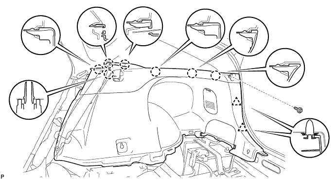
| 23. INSTALL TONNEAU COVER HOLDER CAP (for RH Side) |
| 24. INSTALL LUGGAGE HOLD BELT STRIKER ASSEMBLY (for RH Side) |
| 25. INSTALL REAR DECK TRIM COVER |
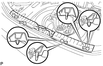 |
Engage the 4 claws and 4 guides to install the rear deck trim cover.
| 26. INSTALL DECK TRIM SERVICE HOLE COVER |
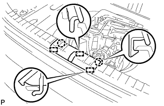 |
Engage the 3 guides.
Engage the 2 claws to install the deck trim service hole cover.
| 27. INSTALL REAR NO. 1 FLOOR BOARD |
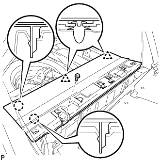 |
Engage the 2 claws and 2 clips.
Install the rear No. 1 floor board with the bolt.
| 28. INSTALL REAR NO. 2 FLOOR BOARD SUB-ASSEMBLY |
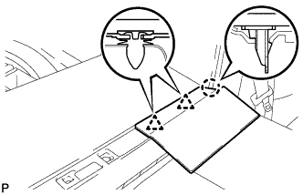 |
Engage the claw and 2 clips to install the rear No. 2 floor board sub-assembly.
| 29. INSTALL REAR NO. 1 FLOOR BOARD SUB-ASSEMBLY |
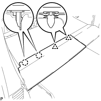 |
Engage the 2 claws and 2 clips to install the rear No. 1 floor board sub-assembly.
| 30. INSTALL DECK FLOOR BOX LH |
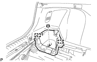 |
Engage the 2 guides.
Install the deck floor box LH with the clip.
| 31. INSTALL REAR NO. 4 FLOOR BOARD |
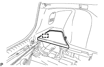 |
Engage the guide to install the rear No. 4 floor board.
| 32. INSTALL TONNEAU COVER ASSEMBLY (w/ Tonneau Cover) |
Install the tonneau cover assembly.
| 33. INSTALL UPPER INSTRUMENT PANEL ASSEMBLY |
Install the upper instrument panel assembly (Click here).
| 34. INSTALL REAR SIDE SEATBACK ASSEMBLY LH |
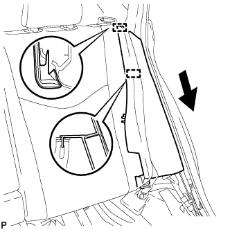 |
Engage the 2 guides as shown in the illustration.
Install the rear side seatback assembly LH with the bolt.
| 35. INSTALL REAR SIDE SEATBACK ASSEMBLY RH |
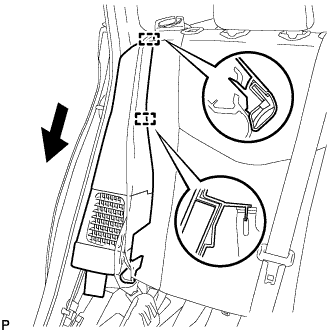 |
Engage the 2 guides as shown in the illustration.
Install the rear side seatback assembly RH with the bolt.
| 36. INSTALL REAR SEAT CUSHION ASSEMBLY |
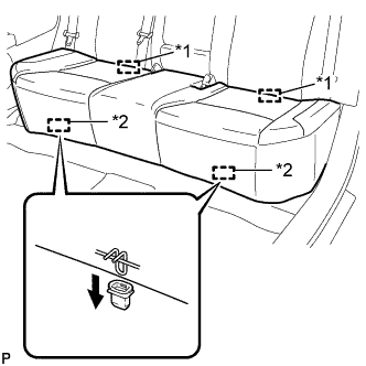 |
Engage the 2 guides of the seat cushion to the seatback.
| *1 | Guide |
| *2 | Hook |
Engage the 2 front hooks of the seat cushion to the vehicle body.
| 37. INSTALL CENTER PILLAR GARNISH LH |
Pass the floor anchor of the front seat outer seat belt assembly LH through the center pillar garnish LH.
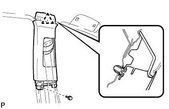 |
Engage the clip.
Install the center pillar garnish LH with the screw.
| 38. INSTALL CENTER PILLAR LOWER GARNISH LH |
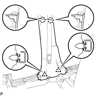 |
Engage the 2 claws and 2 clips to install the center pillar lower garnish LH.
| 39. CONNECT FRONT SEAT OUTER BELT ASSEMBLY LH |
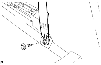 |
Install the floor end of the front seat outer belt assembly with the bolt.
Check if the ELR locks.
With the belt assembly installed, check that the belt locks when it is pulled out quickly.
| 40. INSTALL LAP BELT OUTER ANCHOR COVER (for LH Side) |
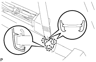 |
Engage the 3 claws to install the lap belt outer anchor cover.
| 41. INSTALL REAR DOOR OPENING TRIM WEATHERSTRIP LH |
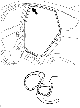 |
Align the alignment mark (Red) on the weatherstrip with the protruding portion on the body indicated by the arrow in the illustration, and install the rear door opening trim weatherstrip LH.
| *1 | Alignment Mark (Red) |
| 42. INSTALL REAR DOOR SCUFF PLATE LH |
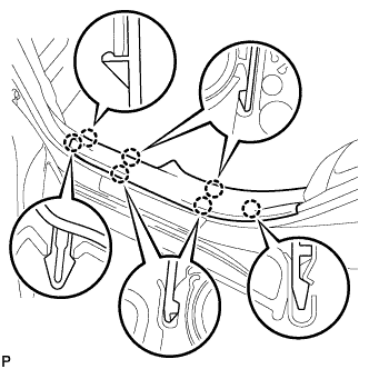 |
Engage the 7 claws to install the rear door scuff plate LH.
| 43. INSTALL FRONT PILLAR GARNISH LH |
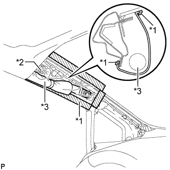 |
Remove the protective cover.
| *1 | Adhesive Tape |
| *2 | Protective Cover |
| *3 | Curtain Shield Airbag Assembly |
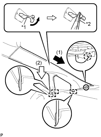 |
Make sure that the front pillar garnish clip is not damaged.
| *1 | Front Pillar Garnish Clip |
| *2 | Protective Tape |
Engage the claw to direction indicated by the arrow (1).
Engage the 3 guides to direction indicated by the arrow (2).
Turn the end of the front pillar garnish clip 90° with needle-nosed pliers and install it to the front pillar garnish LH.
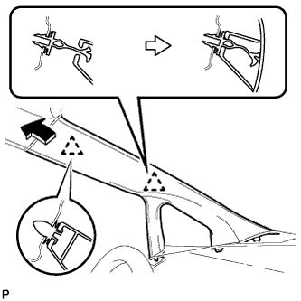 |
Engage the 2 clips to install the front pillar garnish LH.
| 44. INSTALL FRONT DOOR OPENING TRIM WEATHERSTRIP LH |
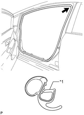 |
Align the alignment mark (Yellow) on the weatherstrip with the protruding portion on the body indicated by the arrow in the illustration, and install the front door opening trim weatherstrip LH.
| *1 | Alignment Mark (Yellow) |
| 45. INSTALL COWL SIDE TRIM SUB-ASSEMBLY LH |
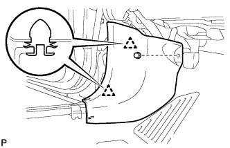 |
Engage the 2 clips.
Install the cowl side trim board LH with the clip.
| 46. INSTALL FRONT DOOR SCUFF PLATE LH |
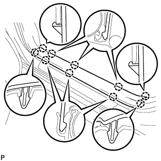 |
Engage the 10 claws to install the front door scuff plate LH.
| 47. INSTALL CENTER PILLAR GARNISH RH |
| 48. INSTALL CENTER PILLAR LOWER GARNISH RH |
| 49. CONNECT FRONT SEAT OUTER BELT ASSEMBLY RH |
| 50. INSTALL LAP BELT OUTER ANCHOR COVER (for RH Side) |
| 51. INSTALL REAR DOOR OPENING TRIM WEATHERSTRIP RH |
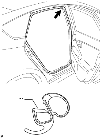 |
Align the alignment mark (Blue) on the weatherstrip with the protruding portion on the body indicated by the arrow in the illustration, and install the rear door opening trim weatherstrip RH.
| *1 | Alignment Mark (Blue) |
| 52. INSTALL REAR DOOR SCUFF PLATE RH |
| 53. INSTALL FRONT PILLAR GARNISH RH |
| 54. INSTALL FRONT DOOR OPENING TRIM WEATHERSTRIP RH |
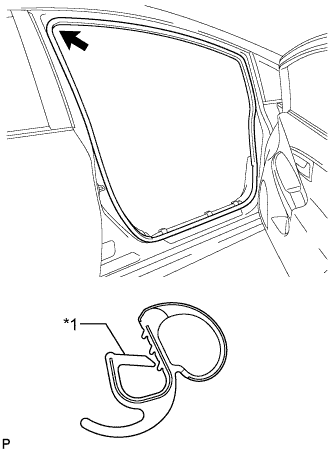 |
Align the alignment mark (White) on the weatherstrip with the protruding portion on the body indicated by the arrow in the illustration, and install the front door opening trim weatherstrip RH.
| *1 | Alignment Mark (White) |
| 55. INSTALL COWL SIDE TRIM SUB-ASSEMBLY RH |
| 56. INSTALL FRONT DOOR SCUFF PLATE RH |
| 57. CONNECT CABLE TO NEGATIVE BATTERY TERMINAL |
| 58. INSTALL REAR NO. 3 FLOOR BOARD |
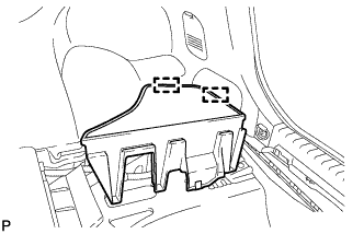 |
Engage the 2 guides to install the rear No. 3 floor board.
| 59. INSTALL REAR DECK FLOOR BOX |
Install the rear deck floor box.
| 60. INSTALL REAR NO. 2 FLOOR BOARD (for Separate Type) |
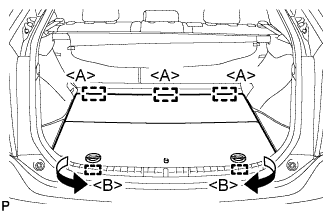 |
Engage the 3 guides <A>.
Engage the 2 guides <B> and install the rear No. 2 floor board as shown in the illustration.
| 61. INSPECT SRS WARNING LIGHT |
Inspect the SRS warning light (Click here).
| 62. ADJUST LANE RECOGNITION CAMERA SENSOR ASSEMBLY (w/ Lane Keeping Assist System) |
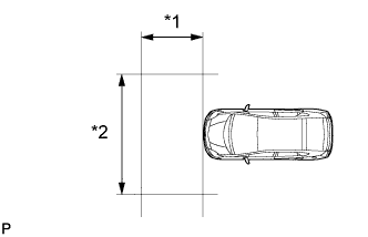 |
| *1 | 1.5 m or more |
| *2 | 3 m or more |
Prepare for beam axis learning.
Move the vehicle to a level surface.
Make sure the engine oil in the vehicle is at the specified level.
Make sure the engine coolant in the vehicle is at the specified level.
Make sure the fuel tank is full.
Make sure the spare tire is in the vehicle.
Make sure the standard tools are in the vehicle.
Make sure nobody is in the vehicle.
Make sure no extra loads are in the vehicle.
Adjust the tire pressures to the specified pressure.
Clean the windshield.
If the lens of the lane recognition camera sensor is dirty, apply a small amount of lens cleaner to a clean and soft cloth, and clean the lens.
Perform the front wheel alignment adjustment.
Perform the front wheel alignment adjustment (Click here).
Perform the rear wheel alignment adjustment.
Perform the rear wheel alignment adjustment (Click here).
Create a target sheet.
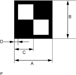  |
Print or copy the illustration . Check that the dimensions are +/- 5 mm (0.197 in.) of the ones in the table below.
| Area | Specification |
| A | 160 mm (6.30 in.) |
| B | 160 mm (6.30 in.) |
| C | 80 mm (3.15 in.) |
| D | 16 mm (0.630 in.) |
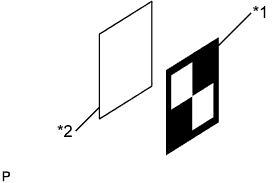 |
Attach the target sheet.
| *1 | Target Sheet |
| *2 | Cardboard, etc. |
Place the prepared target sheet on a piece of cardboard of the same size with the black area on the top right, as shown in the illustration. Then use double-sided tape to fix the target sheet in place.
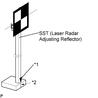 |
Hang a weight with a pointed tip from the center of the target sheet. Then, with double-sided tape, attach the target sheet to the reflector so that the weight aligns with the mark-off line of SST (laser radar adjusting reflector).
| *1 | Pointed Tip Weight |
| *2 | Mark-off Line |
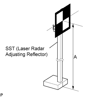 |
Move the reflector up and down to position the center of the target at the height shown in the illustration, and fix it in place.
Measure the target placement point.
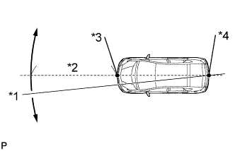 |
From the center of the front and back bumpers (center of the emblems), hang a weight with a pointed tip, and mark the front bumper center point A and the rear bumper center point B on the ground.
| *1 | Line |
| *2 | Approx. 2 m |
| *3 | Point A |
| *4 | Point B |
Draw a line that connects points A and B, and extend the line approximately 2 m (6.56 ft.) beyond the front of the vehicle.
Mark point C 1220 mm (4.00 ft.) from the front bumper center point A (placement point 1).
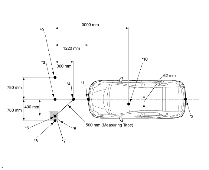
| *1 | Point A | *2 | Point B |
| *3 | Placement Point 1 Point C | *4 | Point D |
| *5 | Line E | *6 | Point F |
| *7 | Place Tape (Gray Area) Approx. 400 mm from Point C | *8 | Placement Point 2 Point G |
| *9 | Placement Point 3 Point H | *10 | Lane Recognition Camera Sensor Position |
From point C, move 300 mm (11.8 in.) towards the front bumper center point A and mark point D.
From point C, place marking tape at the point 400 mm (1.30 ft.) perpendicular to the line that connects points A and B.
Using a measuring tape of 5 m (16.41 ft.) or more, and point D as the center point, draw the part of a 500 mm (1.64 ft.) circle that overlaps the marking tape (line E).
Mark point F where the following intersect: 1) from point C, the point that is 400 mm (1.30 ft.) perpendicular from the line that connects point A and B; and 2) line E.
Set the measuring tape from point C to F. Then mark point G 780 mm (2.56 ft.) from point C (line extending from point C to F) (placement point 2).
Set the measuring tape from point F to C. Then mark point H 780 mm (2.56 ft.) beyond point C (placement point 3).
Set a string between points G and H, and draw a line on the ground (target placement line).
Measure lane recognition camera sensor height.
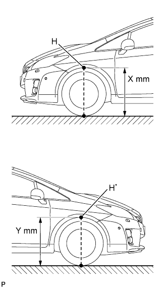 |
Measure the distance (X mm or in.) from the ground to point H for the front left wheel arch.
Measure the distance (Y mm or in.) from the ground to point H' for the front right wheel arch.
The average of the 2 distances (X mm or in, Y mm or in.) plus 617 mm (24.3 in.) is the height of the lane recognition camera sensor.
Memorize camera/target position.
When using the Techstream:
Input the measured height of the lane recognition camera sensor and the horizontal position of the camera "-62 mm (-2.44 in.)" into the input screen. Then press the "Enter" button on the display screen.
Input "3000 mm (118 in.)" for the distance from the camera to the target and "986 mm (38.8 in.)" for the height of the target into the input screen. Then press the "Enter" button on the display screen.
Press the "Exit" button to finish the camera/target position memory mode.
Perform beam axis learning.
Select "Chassis" from the display screen.
Select "Lane Keeping Assist" from the display screen.*1
Select "Utility" from the display screen.
Select "Camera Axis Adjust" from the display screen.
Follow the Techstream display, and continue with the adjustment.
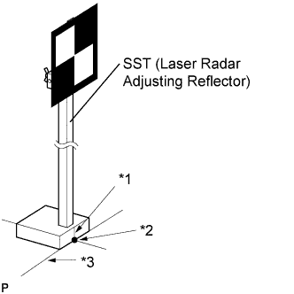 |
Align the target sheet with the target placement line, and align the mark-off line with placement point 1 (point C).
| *1 | Mark-off Line |
| *2 | Point C |
| *3 | Target Placement Line |
Check that the screen displays beam axis learning for target 1, then press the "Enter" button on the display screen.
|
Align the target sheet with the target placement line, and align the mark-off line with placement point 2 (point G).
| *1 | Mark-off Line |
| *2 | Point G |
| *3 | Target Placement Line |
Check that the screen displays beam axis learning for target 2, then press the "Enter" button on the display screen.
|
Align the target sheet with the target placement line, and align the mark-off line with placement point 3 (point H).
| *1 | Mark-off Line |
| *2 | Point H |
| *3 | Target Placement Line |
Check that the screen displays beam axis learning for target 3, then press the "Enter" button on the display screen.
Press the "Exit" button to finish the beam axis learning mode.