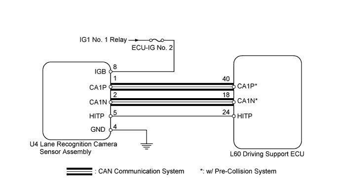
DTC U0122 Lost Communication with Vehicle Dynamics Control Module |
DTC U0123 Lost Communication with Yaw Rate Sensor Module |
DTC U0131 Lost Communication with Power Steering Control Module |
DTC U1104 Lost Communication with Driving Support ECU |
| DTC No. | DTC Detection Condition | Trouble Area |
| U0122 | While power switch is on (IG), communication stop from brake booster with master cylinder (skid control ECU) to driving support ECU continues for 1 second or more |
|
| U0123 | While power switch is on (IG), communication stop from yaw rate sensor to driving support ECU continues for 1 second or more |
|
| U0131 | While power switch is on (IG), communication stop from power steering control ECU to driving support ECU continues for 1 second or more |
|
| U1104 | While power switch is on (IG), communication stop from driving support ECU to skid control ECU assembly, lane recognition camera sensor assembly or power steering control ECU continues for 1 second or more |
|
| 1.CHECK DTC OUTPUT |
Using the Techstream, enter the following menus: All ECUs / Lane Keeping Assist / Trouble Codes.
Check for DTCs (Click here).
| Result | Proceed to |
| DTC U1104 is output | A |
| DTC other than U1104 is output | B |
|
| ||||
| A | |
 |
| 2.CHECK CAN COMMUNICATION SYSTEM |
Select "CAN Bus Check" from the "System Selection Menu" screen on the Techstream.
Select "Communication Malfunction DTC" from the "CAN Bus Check" screen, and then select "Enter".
|
| ||||
| OK | |
|
| 3.CHECK HARNESS AND CONNECTOR (LANE RECOGNITION CAMERA SENSOR ASSEMBLY POWER SOURCE) |
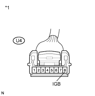 |
Disconnect the lane recognition camera sensor assembly connector.
Turn the power switch on (IG).
Measure the voltage according to the value(s) in the table below.
| Tester Connection | Condition | Specified Condition |
| U4-8 (IGB) - Body ground | Power switch on (IG) | 10 to 14 V |
| *1 | Front view of wire harness connector (to Lane Recognition Camera Sensor Assembly) |
Reconnect the recognition camera sensor connector.
|
| ||||
| OK | |
|
| 4.CHECK HARNESS AND CONNECTOR (LANE RECOGNITION CAMERA SENSOR ASSEMBLY GND CIRCUIT) |
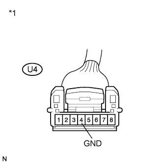 |
Disconnect the lane recognition camera sensor assembly connector.
Measure the resistance according to the value(s) in the table below.
| Tester Connection | Condition | Specified Condition |
| U4-4 (GND) - Body ground | Always | Below 1 Ω |
| *1 | Front view of wire harness connector (to Lane Recognition Camera Sensor Assembly) |
|
| ||||
| OK | |
|
| 5.REPLACE LANE RECOGNITION CAMERA SENSOR ASSEMBLY |
Replace the lane recognition camera sensor assembly (Click here).
Adjust the lane recognition camera assembly (Click here).
| NEXT | |
|
| 6.CHECK DTC OUTPUT |
Using the Techstream, enter the following menus: All ECUs / Lane Keeping Assist / Trouble Codes.
Clear the DTCs (Click here).
Turn the power switch off.
Turn the power switch on (IG).
Drive the vehicle and operate lane keeping assist control.
Recheck for DTCs.
|
| ||||
| OK | ||
 | ||
| ||
