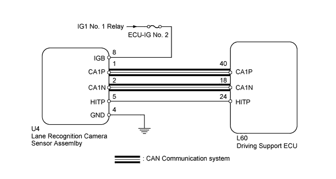
DTC U1119 Lost Communication with Object Recognition ECU (CAN) |
| DTC No. | DTC Detection Condition | Trouble Area |
| U1119 | While power switch is on (IG), communication stop between lane recognition camera sensor and driving support ECU continues for 1 second or more |
|
| 1.CHECK DTC OUTPUT |
Connect the Techstream to the DLC3.
Turn the power switch on (IG).
Clear the DTCs (Click here).
Perform the following to make sure that the DTC detection conditions are met.
Drive the vehicle at a speed for which cruise control operation is possible.
Turn the cruise control main switch on.
Push the -SET switch to activate the cruise control.
Enter the following menus: Powertrain / Radar Cruise / Trouble Codes.
Read the DTCs.
| Result | Proceed to |
| DTC U1119 is output | A |
| DTC other than U1119 is output | B |
|
| ||||
| A | |
 |
| 2.READ VALUE USING TECHSTREAM |
Connect the Techstream to the DLC3.
Turn the power switch on (IG).
Turn the Techstream on.
Enter the following menus: Body Electrical / Pre-Collision 2/ Data List / Recog ECU H Temp Hist.
Confirm the judgment history.
| Tester Display | Measurement Item/Range | Normal Condition | Diagnostic Note |
| Recog ECU H Temp Hist | Lane-recognition ECU temperature condition history/ ON or OFF | ON: No history of excessive temperature OFF: History of excessive temperature | - |
| Result | Proceed to |
| ON is displayed | A |
| OFF is displayed | B |
|
| ||||
| A | |
|
| 3.CHECK HARNESS OR CONNECTOR (DRIVING SUPPORT ECU - LANE RECOGNITION CAMERA SENSOR) |
Disconnect the driving support ECU connector and lane recognition camera sensor connector.
Measure the resistance according to the value(s) in the table below.
| Tester Condition | Condition | Specified Condition |
| U4-5 (HITP) - L60-24 (HITP) | Always | Below 1 Ω |
| U4-5 (HITP) or L60-24 (HITP) - Body ground | Always | 10 kΩ or higher |
Reconnect the connectors.
|
| ||||
| OK | ||
 | ||
| ||
| 4.REPAIR OR REPLACE HARNESS OR CONNECTOR (DRIVING SUPPORT ECU - LANE RECOGNITION CAMERA SENSOR) |
Repair or replace harness or connector.
| NEXT | |
|
| 5.CHECK DTC OUTPUT |
Connect the Techstream to the DLC3.
Turn the power switch on (IG).
Clear the DTCs (Click here).
Perform the following to make sure that the DTC detection conditions are met.
Drive the vehicle at a speed for which cruise control operation is possible.
Turn the cruise control main switch on.
Push the -SET switch to activate the cruise control.
Enter the following menus: Powertrain / Radar Cruise / Trouble Codes.
Read the DTCs.
| Result | Proceed to |
| DTC U1119 is not output | A |
| DTC U1119 is output | B |
|
| ||||
| A | ||
| ||
| ||
| 6.CHECK CAN COMMUNICATION SYSTEM |
Check CAN communication system (Click here).
|
| ||||
| OK | |
|
| 7.REPLACE LANE RECOGNITION CAMERA SENSOR ASSEMBLY |
Replace the lane recognition camera sensor assembly (Click here).
Adjust the lane recognition camera sensor (Click here).
| NEXT | |
|
| 8.CHECK DTC OUTPUT |
Connect the Techstream to the DLC3.
Turn the power switch on (IG).
Clear the DTCs (Click here).
Perform the following to make sure that the DTC detection conditions are met.
Drive the vehicle at a speed of 40 km/h (25 mph) or more.
Turn the cruise control main switch on.
Push the -SET switch to activate the cruise control.
Enter the following menus: Powertrain / Radar Cruise / Trouble Codes.
Read the DTCs.
| Result | Proceed to |
| DTC U1119 is not output | A |
| DTC U1119 is output | B |
|
| ||||
| A | ||
| ||
| ||

