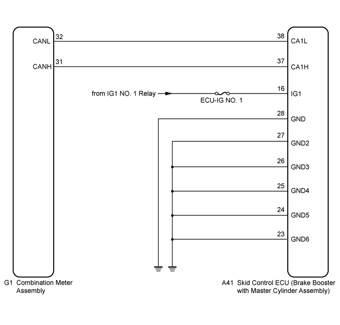
ELECTRONICALLY CONTROLLED BRAKE SYSTEM > ABS Warning Light Remains ON |
| 1.CHECK CAN COMMUNICATION SYSTEM |
Check if CAN communication system DTCs are output (Click here).
| Result | Proceed to |
| DTC is not output. | A |
| DTC is output. | B |
|
| ||||
| A | |
 |
| 2.CHECK IF SKID CONTROL ECU CONNECTOR IS SECURELY CONNECTED |
Check if the skid control ECU (brake booster with master cylinder assembly) connector is securely connected.
|
| ||||
| OK | |
|
| 3.CHECK AUXILIARY BATTERY |
Check the auxiliary battery voltage.
| Tester Connection | Condition | Specified Condition |
| Auxiliary battery | Power switch on (IG) | 11 to 14 V |
| Auxiliary battery | Power switch on (ready) | 11 to 15.5 V |
|
| ||||
| OK | |
|
| 4.CHECK HARNESS AND CONNECTOR (IG1 TERMINAL) |
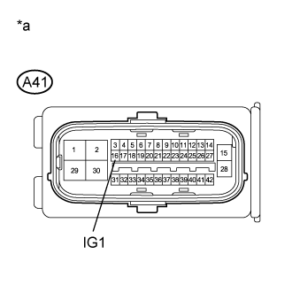 |
Disconnect the skid control ECU (brake booster with master cylinder assembly) connector.
Turn the power switch on (IG).
Measure the voltage according to the value(s) in the table below.
| Tester Connection | Condition | Specified Condition |
| A41-16 (IG1) - Body ground | Power switch on (IG) | 11 to 14 V |
| *a | Front view of wire harness connector (to Skid Control ECU (Brake Booster with Master Cylinder Assembly)) |
|
| ||||
| OK | |
|
| 5.CHECK HARNESS AND CONNECTOR (GND TERMINAL) |
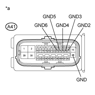 |
Turn the power switch off (lock).
Measure the resistance according to the value(s) in the table below.
| Tester Connection | Condition | Specified Condition |
| A41-28 (GND) - Body ground | Always | Below 1 Ω |
| A41-27 (GND2) - Body ground | Always | Below 1 Ω |
| A41-26 (GND3) - Body ground | Always | Below 1 Ω |
| A41-25 (GND4) - Body ground | Always | Below 1 Ω |
| A41-24 (GND5) - Body ground | Always | Below 1 Ω |
| A41-23 (GND6) - Body ground | Always | Below 1 Ω |
| *a | Front view of wire harness connector (to Skid Control ECU (Brake Booster with Master Cylinder Assembly)) |
|
| ||||
| OK | |
|
| 6.INSPECT COMBINATION METER ASSEMBLY |
Reconnect the skid control ECU (brake booster with master cylinder assembly) connector.
Perform the Active Test of the combination meter assembly (meter CPU) using the intelligent tester (Click here).
Check the combination meter assembly.
| Result | Proceed to |
| OK (for LHD) | A |
| OK (for RHD) | B |
| NG | C |
|
| ||||
|
| ||||
| A | ||
 | ||
| ||
