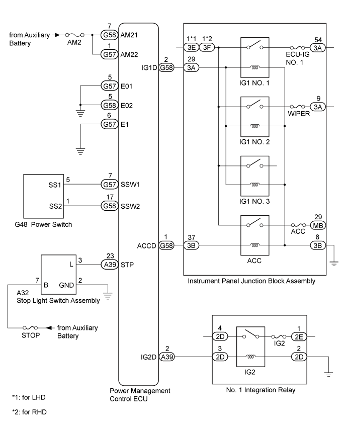
SMART ENTRY AND START SYSTEM (for Start Function) > Power Source Mode does not Change to ON (IG and ACC) |
| Problem Symptom | Data List Item | Active Test Item |
| Power source mode does not change to on (IG) or on (ACC) | Power Source Control
| - |
| 1.CHECK WIRELESS DOOR LOCK CONTROL SYSTEM |
Check the wireless door lock function by operating the electrical key transmitter sub-assembly.
|
| ||||
| OK | |
 |
| 2.CHECK HARNESS AND CONNECTOR (POWER SOURCE) |
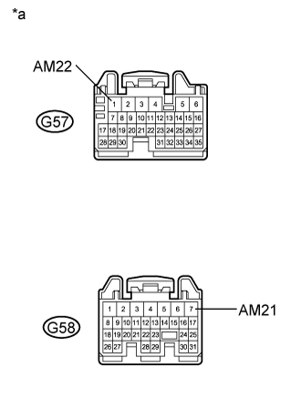 |
Disconnect the G57 and G58 connectors from the power management control ECU.
Measure the voltage according to the value(s) in the table below.
| Tester Connection | Condition | Specified Condition |
| G57-1 (AM22) - Body ground | Power switch off | 11 to 14 V |
| G58-7 (AM21) - Body ground | Power switch off | 11 to 14 V |
| *a | Front view of wire harness connector (to Power Management Control ECU) |
|
| ||||
| OK | |
|
| 3.CHECK HARNESS AND CONNECTOR (GROUND) |
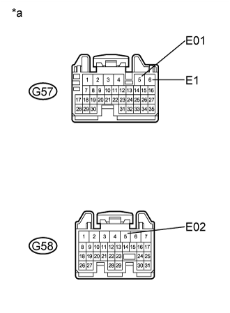 |
Measure the resistance according to the value(s) in the table below.
| Tester Connection | Condition | Specified Condition |
| G57-5 (E01) - Body ground | Always | Below 1 Ω |
| G57-6 (E1) - Body ground | Always | Below 1 Ω |
| G58-5 (E02) - Body ground | Always | Below 1 Ω |
| *a | Front view of wire harness connector (to Power Management Control ECU) |
|
| ||||
| OK | |
|
| 4.CHECK SMART ENTRY AND START SYSTEM |
Remove the transmitter battery from the electrical key transmitter sub-assembly (Click here).
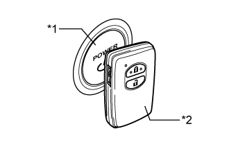 |
With the brake pedal depressed, hold the electrical key transmitter sub-assembly near the power switch and check if the power source mode changes.
| Result | Proceed to |
| The power source mode does not change. | A |
| The power source mode changes. | B |
| *1 | Power Switch |
| *2 | Electrical Key Transmitter Sub-assembly |
|
| ||||
| A | |
|
| 5.READ VALUE USING INTELLIGENT TESTER |
Connect the intelligent tester to the DLC3.
Turn the intelligent tester on.
Enter the following menus: Body / Power Source Control / Data List.
Read the Data List according to the display on the intelligent tester.
| Tester Display | Measurement Item/Range | Normal Condition | Specified Condition |
| Stop Light Switch1 | State of brake pedal/ON or OFF | ON: Brake pedal depressed OFF: Brake pedal released |
|
|
| ||||
| OK | |
|
| 6.READ VALUE USING INTELLIGENT TESTER |
Read the Data List according to the display on the intelligent tester.
| Tester Display | Measurement Item/Range | Normal Condition | Diagnostic Note |
| Power Supply Condition | Power supply state/IG2 ON, ST ON, All OFF, IG1 ON or ACC ON | All OFF: Power switch off ACC ON: Power switch on (ACC) IG1 ON: Power switch on (IG) (IG1 relay on) IG2 ON: Power switch on (IG) (IG2 relay on) ST ON: Sending hybrid control system start request signal | Since the IG1 and IG2 relays turn on at approximately the same time, IG1 ON may not be displayed (the IG1 relay turns on for a very short time). |
With the power switch off and brake pedal depressed, hold the electrical key transmitter sub-assembly near the power switch for 2 seconds or more and read the Data List.
|
| ||||
| OK | |
|
| 7.CHECK POWER MANAGEMENT CONTROL ECU |
Read the Data List according to the display on the intelligent tester.
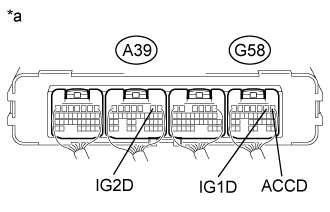 |
Measure the voltage according to the value(s) in the table below.
| *a | Component with harness connected (Power Management Control ECU) |
Read the Data List according to the display on the intelligent tester.
| Tester Display | Measurement Item/Range | Normal Condition | Diagnostic Note |
| Power Supply Condition | Power supply state/IG2 ON, ST ON, All OFF, IG1 ON or ACC ON | All OFF: Power switch off ACC ON: Power switch on (ACC) IG1 ON: Power switch on (IG) (IG1 relay on) IG2 ON: Power switch on (IG) (IG2 relay on) ST ON: Sending hybrid control system start request signal | Since the IG1 and IG2 relays turn on at approximately the same time, IG1 ON may not be displayed (the IG1 relay turns on for a very short time). |
Measure the voltage while checking the Data List on the intelligent tester.
| Tester Connection | Condition | Specified Condition |
| G58-2 (IG1D) - Body ground | Power switch off | 1 V or less |
| Power switch on (ACC) | 1 V or less | |
| Power switch on (IG) | 9 V or higher | |
| A39-2 (IG2D) - Body ground | Power switch off | 1 V or less |
| Power switch on (ACC) | 1 V or less | |
| Power switch on (IG) | 9 V or higher | |
| G58-1 (ACCD) - Body ground | Power switch off | 1 V or less |
| Power switch on (IG) | 8.5 V or higher | |
| Power switch on (ACC) | 8.5 V or higher |
|
| ||||
| OK | ||
 | ||
| ||
| 8.READ VALUE USING INTELLIGENT TESTER |
Read the Data List according to the display on the intelligent tester.
| Tester Display | Measurement Item/Range | Normal Condition | Diagnostic Note |
| Start Switch1 | Power switch 1 status/ON or OFF | ON: Power switch pressed OFF: Power switch not pressed |
|
| Start Switch2 | Power switch 2 status/ON or OFF | ON: Power switch pressed OFF: Power switch not pressed |
|
| Result | Proceed to |
| NG | A |
| OK | B |
|
| ||||
| A | |
|
| 9.INSPECT POWER SWITCH |
Inspect the power switch (Click here).
|
| ||||
| OK | |
|
| 10.CHECK HARNESS AND CONNECTOR (POWER MANAGEMENT CONTROL ECU - POWER SWITCH) |
Disconnect the G57 and G58 connectors from the power management control ECU.
Disconnect the G48 connector from the power switch.
Measure the resistance according to the value(s) in the table below.
| Tester Connection | Condition | Specified Condition |
| G57-7 (SSW1) - G48-5 (SS1) | Always | Below 1 Ω |
| G58-17 (SSW2) - G48-1 (SS2) | Always | Below 1 Ω |
| G57-7 (SSW1) or G48-5 (SS1) - Body ground | Always | 10 kΩ or higher |
| G58-17 (SSW2) or G48-1 (SS2) - Body ground | Always | 10 kΩ or higher |
|
| ||||
| OK | ||
| ||
| ||
| 11.CHECK HARNESS AND CONNECTOR (STOP LIGHT SWITCH ASSEMBLY - POWER SOURCE AND BODY GROUND) |
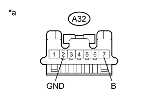 |
Disconnect the A32 connector from stop light switch assembly.
Measure the voltage and resistance according to the value(s) in the table below.
| Tester Connection | Condition | Specified Condition |
| A32-7 (B) - A32-2 (GND) | Power switch off | 11 to 14 V |
| Tester Connection | Condition | Specified Condition |
| A32-2 (GND) - Body ground | Always | Below 1 Ω |
| *a | Front view of wire harness connector (to Stop Light Switch Assembly) |
|
| ||||
| OK | |
|
| 12.CHECK STOP LIGHT SWITCH ASSEMBLY |
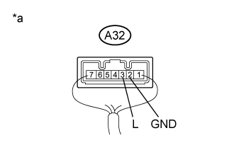 |
Reconnect the A32 connector from stop light switch assembly.
Measure the voltage according to the value(s) in the table below.
| Tester Connection | Switch Condition | Specified Condition |
| A32-3 (L) - A32-2 (GND) | Power switch off, Brake pedal not depressed | Below 1 V |
| A32-3 (L) - A32-2 (GND) | Power switch off, Brake pedal depressed | 11 to 14 V |
| *a | Component with harness connected (Stop Light Switch Assembly) |
|
| ||||
| OK | |
|
| 13.CHECK HARNESS AND CONNECTOR (POWER MANAGEMENT CONTROL ECU - STOP LIGHT SWITCH ASSEMBLY) |
Disconnect the A32 connector from the stop light switch assembly.
Measure the resistance according to the value(s) in the table below.
| Tester Connection | Condition | Specified Condition |
| A39-23 (STP) - A32-3 (L) | Always | Below 1 Ω |
| A39-23 (STP) or A32-3 (L) - Body ground | Always | 10 kΩ or higher |
Reconnect the A32 stop light switch assembly connector.
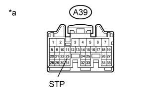 |
Disconnect the A39 connector from the power management control ECU.
Measure the voltage according to the value(s) in the table below.
| Tester Connection | Condition | Specified Condition |
| A39-23 (STP) - Body ground | Brake pedal released | 1 V or less |
| Brake pedal depressed | 9 V or higher |
| *a | Front view of wire harness connector (to Power Management Control ECU) |
|
| ||||
| OK | ||
| ||
| ||
| 14.CHECK FOR DTC |
Enter the following menus:
for Entry&Start: Body / Entry&Start / Trouble Codes.
Check for DTCs.
| Result | Proceed to |
The following DTCs are not output:
| A |
| DTC B2785 is not output but DTC B2287 is output. | B |
| DTCs other than B2287 are output. | C |
|
| ||||
|
| ||||
| A | ||
| ||
| ||

