Home › Engine / Hybrid System › 1NZ-FXE ENGINE MECHANICAL › ENGINE ASSEMBLY

ENGINE ASSEMBLY > REMOVAL

for Preparation Click here


CAUTION:
The engine assembly with transmission is very heavy. Be sure to follow the procedure described in the repair manual, or the engine lifter may suddenly drop.


1. PRECAUTION

CAUTION:
The vehicle has a hybrid system that operates at voltages up to 650 V. The hybrid system uses an HV battery that contains an electrolyte which is a strong alkali solution that includes potassium hydroxide. Be sure to follow the instructions in this manual to handle the system correctly. Failure to do so may result in serious injury or electrocution (Click here).

NOTICE:
After turning the power switch off, waiting time may be required before disconnecting the cable from the negative (-) auxiliary battery terminal. Therefore, make sure to read the disconnecting the cable from the negative (-) auxiliary battery terminal notices before proceeding with work (Click here).


2. RECOVER REFRIGERANT FROM REFRIGERATION SYSTEM
  1. Start the hybrid system.

  1. Operate the cooler compressor under the conditions show below:
    Item
    Condition
    Engine Speed
    Idling
    Operating Time
    3 minutes or more
    A/C Switch Status
    ON
    Blower Switch Status
    HI
    Set Temperature
    MAX COOL
    This causes most of the compressor oil from the various components of the A/C system to collect in the A/C compressor.

    HINT:
    It is not necessary to operate the cooler compressor if the A/C does not operate because of compressor lock, etc.

  1. Stop the engine.

  1. Recover the refrigerant from the A/C system using a refrigerant recovery unit.

    HINT:
    Use the refrigerant recovery unit in accordance with the manufacturer's instruction manual.


3. DISCHARGE FUEL SYSTEM PRESSURE
(Click here)


4. REMOVE SERVICE PLUG GRIP
(Click here)


5. DISCONNECT CABLE FROM NEGATIVE AUXILIARY BATTERY TERMINAL
(Click here)


6. REMOVE ENGINE UNDER COVER LH


7. REMOVE ENGINE UNDER COVER RH


8. DRAIN ENGINE OIL
  1. Remove the oil filler cap.

  1. Remove the oil pan drain plug and gasket, and drain the oil into a container.

  1. Clean and install the oil drain plug with a new gasket.

    Torque:
    38 N*m{ 382 kgf*cm , 28 ft.*lbf }


9. DRAIN COOLANT (for Engine)

NOTICE:
Do not remove the water filler cap sub-assembly, engine drain cock plug or radiator drain cock plug while the engine and radiator are still hot. Pressurized, hot engine coolant and steam may be released and cause serious burns.

  1. Loosen the radiator drain cock plug.


  1. Remove the water filler cap sub-assembly and drain the coolant.
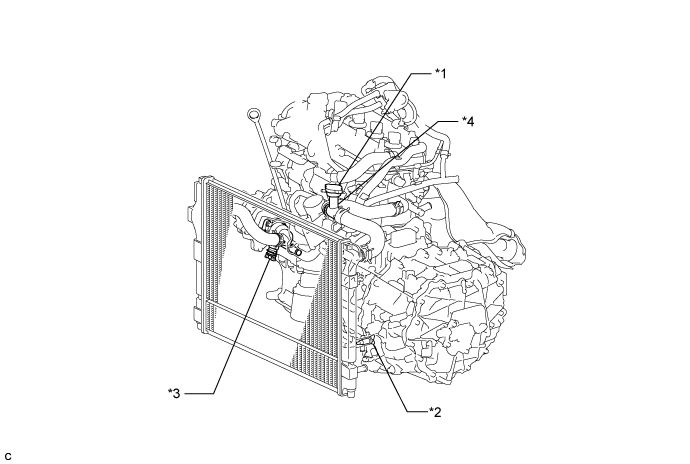

    A267952E01


    Text in Illustration 
    *1
    Water Filler Cap Sub-assembly
    *2
    Radiator Drain Cock Plug
    *3
    Engine Drain Cock Plug
    *4
    Water Filler

    HINT:
    Collect the coolant in a container and dispose of it according to the regulations in your area.
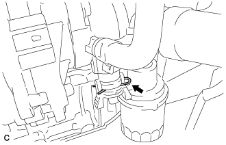


    A267960
  1. Remove the stop ring.


    A268695E01
  1. Connect the hose to the engine drain cock plug.
    Text in Illustration 
    *1
    Hose

  1. Pull out the engine drain cock plug and drain the coolant.


10. DRAIN COOLANT (for Inverter)

NOTICE:
  1. Do not reuse the drained coolant because it may contain foreign matter.
  2. Collect the drained coolant and measure its volume to establish a benchmark. When adding coolant, make sure to add more coolant than the measured amount.

  1. Remove the reserve tank cap.

    CAUTION:
    To avoid the danger of being burned, do not remove the reserve tank cap while the coolant for the inverter is still hot.


    A266681
  1. Loosen the radiator drain cock plug and drain the coolant.

    CAUTION:
    Use caution when handling coolant immediately after driving or in summer because it may be hot.

  1. Tighten the radiator drain cock plug.


11. DRAIN HYBRID TRANSAXLE FLUID


    C249711
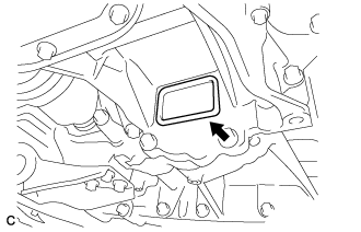
  1. Using a 10 mm hexagon socket wrench, remove the filler plug and gasket.


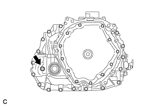
    C249712
  1. Using a 10 mm hexagon socket wrench, remove the drain plug and gasket to drain the hybrid transaxle fluid.

  1. Using a 10 mm hexagon socket wrench, install the drain plug and a new gasket.

    Torque:
    50 N*m{ 510 kgf*cm , 37 ft.*lbf }


12. REMOVE WINDSHIELD WIPER MOTOR AND LINK ASSEMBLY
(Click here)


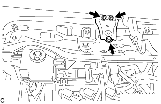
13. REMOVE INNER COWL TOP TO COWL BRACE (for LHD)


    C250011
  1. Remove the 3 bolts and inner cowl top to cowl brace.


14. REMOVE INNER COWL TOP TO COWL BRACE (for RHD)


    C249834
  1. Remove the 3 bolts and inner cowl top to cowl brace.


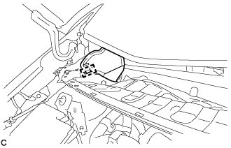
15. REMOVE FRONT AIR SHUTTER SEAL (for LHD)


    C250012
  1. Disengage the clamp to remove the front air shutter seal.


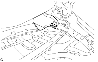
16. REMOVE FRONT AIR SHUTTER SEAL (for RHD)


    C249836
  1. Disengage the clamp to remove the front air shutter seal.


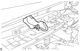
17. REMOVE FRONT NO. 1 VENTILATOR SEAL (for LHD)


    C250013
  1. Disengage the clamp to remove the front No. 1 ventilator seal.


18. REMOVE FRONT NO. 1 VENTILATOR SEAL (for RHD)


    C249835
  1. Disengage the clamp to remove the front No. 1 ventilator seal.


19. REMOVE OUTER COWL TOP PANEL SUB-ASSEMBLY (for LHD)


    C250014
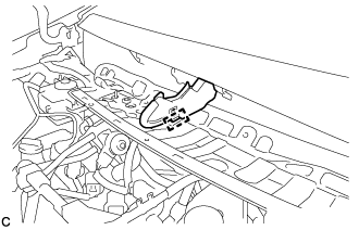
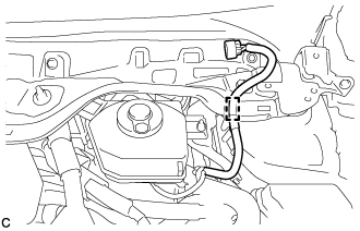
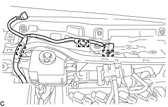
  1. Disengage the clamp to separate the wire harness from the outer cowl top panel sub-assembly.


    C250015
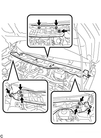
  1. Remove the 8 bolts, nut and outer cowl top panel sub-assembly.


20. REMOVE OUTER COWL TOP PANEL SUB-ASSEMBLY (for RHD)


    C256179
  1. Disengage the 3 clamps to separate the wire harness from the outer cowl top panel sub-assembly.


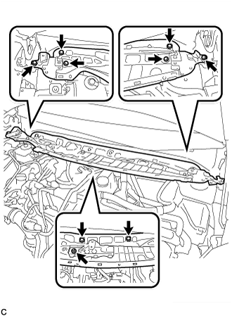
    C249838
  1. Remove the 8 bolts, nut and outer cowl top panel sub-assembly.


21. REMOVE INVERTER WITH CONVERTER ASSEMBLY
(Click here)


22. REMOVE AIR CLEANER CAP SUB-ASSEMBLY


    A267396
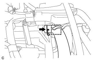
  1. Disconnect the ventilation hose.


    A267397
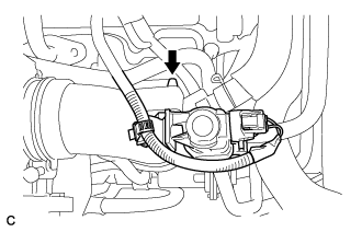
  1. Disconnect the purge VSV.


    A267398
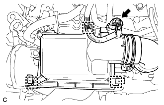
  1. Disconnect the mass air flow meter connector.

  1. Disconnect the wire harness clamp.

  1. Release the 2 clamps.


    A267400
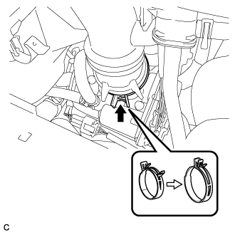
  1. Loosen the hose clamp and remove the air cleaner cap sub-assembly.


23. REMOVE AIR CLEANER CASE SUB-ASSEMBLY
  1. Remove the air cleaner filter element sub-assembly.


    A267683
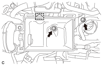
  1. Remove the 2 bolts, grommet and air cleaner case sub-assembly.


24. REMOVE INVERTER BRACKET ASSEMBLY

CAUTION:
Wear insulated gloves.


    A268005
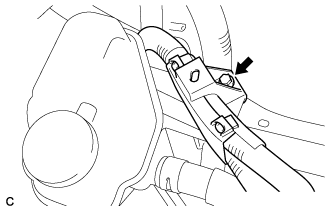
  1. Remove the bolt and separate the motor cable protector.


    A268006
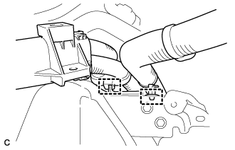
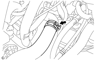
  1. Disconnect the 2 wire harness clamps.


    A268007
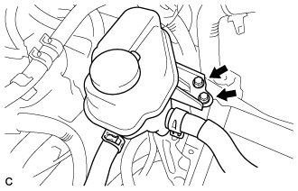
  1. Remove the 2 bolts and separate the inverter reservoir tank assembly.


    A268008
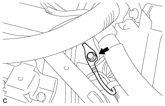
  1. Remove the bolt and disconnect the earth wire.


    A268009
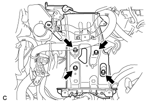
  1. Remove the 4 bolts and inverter bracket assembly.


25. DISCONNECT NO. 1 RADIATOR HOSE


    A267997
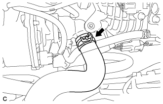
  1. Disconnect the No. 1 radiator hose from the engine assembly.


26. DISCONNECT NO. 2 RADIATOR HOSE


    A267996
  1. Disconnect the No. 2 radiator hose from the engine assembly.


27. DISCONNECT HEATER WATER HOSE


    A267998
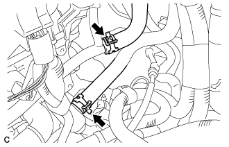
  1. Disconnect the 2 heater water hoses from the engine assembly.


28. DISCONNECT FUEL VAPOR FEED HOSE ASSEMBLY


    A267999
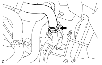
  1. Disconnect the fuel vapor feed hose assembly.


29. DISCONNECT FUEL TUBE SUB-ASSEMBLY


    A268448E01
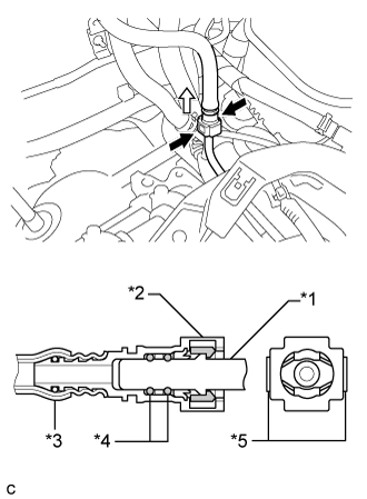
  1. Pinch the retainer of the fuel tube connector, and then pull the fuel tube connector off of the fuel delivery pipe.
    Text in Illustration 
    *1
    Fuel delivery pipe
    *2
    Fuel Tube Connector
    *3
    Nylon Tube
    *4
    O-ring
    *5
    Retainer
    V100135
    Pinch
    V100136
    Pull

    NOTICE:
    1. Check for foreign matter on the fuel tube around the fuel tube connector. Clean it if necessary. Foreign matter can affect the ability of the O-ring to seal the fuel tube connector and fuel delivery pipe.
    2. Do not use any tools to separate the fuel tube connector and fuel delivery.
    3. Do not forcibly bend, kink or twist the nylon tube.
    4. Keep the fuel tube connector and fuel delivery pipe free from foreign matter.
    5. If the fuel tube connector and fuel delivery pipe are stuck, push and pull to release them.
    6. Put the fuel tube connector and fuel delivery pipe in plastic bags to prevent damage and contamination.


30. DISCONNECT ENGINE WIRE (for LHD)


    A268000
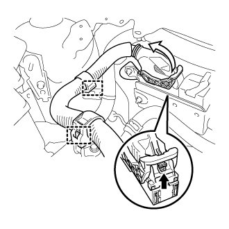
  1. Push the lock on the lever, then raise the lever, and disconnect the ECM connector.

    NOTICE:
    If there is any foreign matter such as mud or water on a connector, clean the connector.

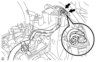
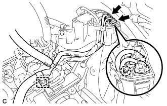
  1. Disconnect the 2 wire harness clamps.


    A268004
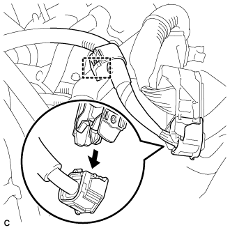
  1. Disconnect the 2 connectors and wire harness clamp.

  1. Using a screwdriver, disengage the claw and disconnect the engine wire from the engine room relay block and junction block assembly.


    A268002
  1. Disconnect the engine wire from the engine room main wire.

  1. Disconnect the wire harness clamp.


31. DISCONNECT ENGINE WIRE (for RHD)


    A268001
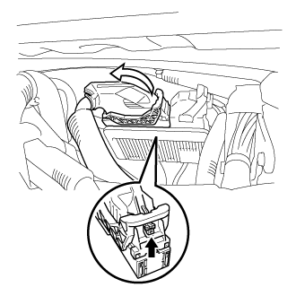
  1. Push the lock on the lever, then raise the lever, and disconnect the ECM connector.

    NOTICE:
    If there is any foreign matter such as mud or water on a connector, clean the connector.


    A268003
  1. Disconnect the 2 connectors and wire harness clamp.

  1. Using a screwdriver, disengage the claw and disconnect the engine wire from the engine room relay block and junction block assembly.


    A268002
  1. Disconnect the engine wire from the engine room main wire.

  1. Disconnect the wire harness clamp.


32. DISCONNECT TRANSMISSION CONTROL CABLE ASSEMBLY


    C249710E01
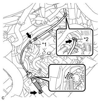
  1. Remove the nut, clip and disconnect the transmission control cable assembly from the No. 1 transmission control cable bracket and transmission control shaft lever.
    Text in Illustration 
    *1
    Transmission Control Cable Clamp
    *2
    Transmission Control Cable Support

  1. Disconnect the transmission control cable assembly from the transmission control cable clamp and transmission control cable support.


33. PLACE FRONT WHEELS FACING STRAIGHT AHEAD


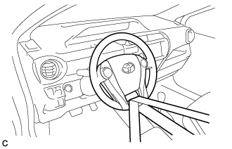
34. SECURE STEERING WHEEL


    C247537
  1. Secure the steering wheel with the seat belt in order to prevent rotation.

    HINT:
    This operation is useful to prevent damage to the spiral cable.


35. REMOVE COLUMN HOLE COVER SILENCER SHEET


    C248046
  1. Remove the 2 clips and the column hole cover silencer sheet.


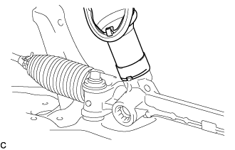
36. SEPARATE STEERING SLIDING YOKE SUB-ASSEMBLY


    C249572E01
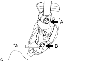
  1. Put matchmarks on the steering sliding yoke sub-assembly and steering gear assembly.
    Text in Illustration 
    *a
    Matchmark

  1. Loosen bolt A.

  1. Remove bolt B.

  1. Separate the steering sliding yoke sub-assembly from the steering gear assembly.


37. DISCONNECT NO. 1 STEERING COLUMN HOLE COVER SUB-ASSEMBLY


    C251700
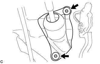
  1. Remove the No. 1 steering column hole cover sub-assembly from the steering link assembly.


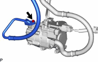
38. DISCONNECT NO. 1 COOLER REFRIGERANT DISCHARGE HOSE


    E234973
  1. Remove the bolt and disconnect the No. 1 cooler refrigerant discharge hose from the compressor with motor assembly.

  1. Remove the O-ring from the No. 1 cooler refrigerant discharge hose.

    NOTICE:
    Seal the openings of the disconnected parts using vinyl tape to prevent entry of moisture and foreign matter.


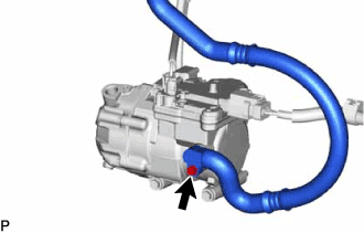
39. DISCONNECT SUCTION HOSE SUB-ASSEMBLY


    E234974
  1. Remove the bolt and disconnect the suction hose sub-assembly from the compressor with motor assembly.

  1. Remove the O-ring from the suction hose sub-assembly.

    NOTICE:
    Seal the openings of the disconnected parts using vinyl tape to prevent entry of moisture and foreign matter.


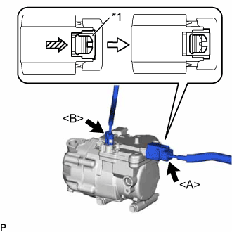
40. REMOVE COMPRESSOR WITH MOTOR ASSEMBLY


    E234971E01
  1. Using a screwdriver, slide the green-colored lock of the connector <A> in the direction indicated by the arrow in the illustration to release it and disconnect the connector.
    Text in Illustration 
    *1
    Green-colored Lock

    CAUTION:
    Make sure to wear insulating gloves.

    NOTICE:
    Insulate the removed terminals and connector with insulating tape.

  1. Disconnect the connector <B>.


    E234975
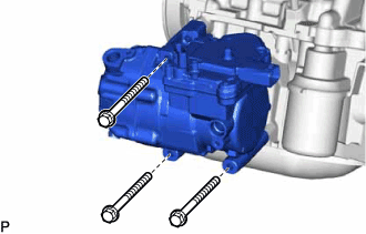
  1. Remove the 3 bolts and the compressor with motor assembly.


41. REMOVE FRONT EXHAUST PIPE ASSEMBLY


    A267686
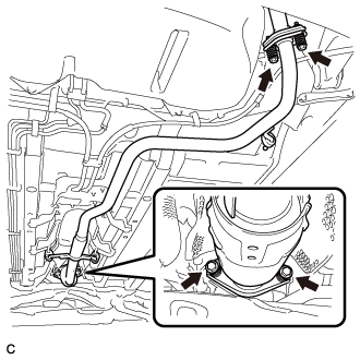
  1. Remove the 4 bolts and 4 compression springs.

  1. Remove the front exhaust pipe assembly from the 3 exhaust pipe supports.

  1. Remove the 2 gaskets from the front exhaust pipe assembly and exhaust manifold.


42. SEPARATE NO. 2 ENGINE ROOM RELAY BLOCK AND NO. 2 JUNCTION BLOCK ASSEMBLY


    A268172
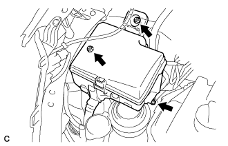
  1. Remove the bolt and 2 nuts, and separate the No. 2 engine room relay block and No. 2 junction block assembly.


43. REMOVE FRONT DRIVE SHAFT ASSEMBLY
(Click here)


44. REMOVE FLYWHEEL HOUSING UNDER COVER


    A268016
  1. Remove the flywheel housing under cover.


45. REMOVE ENGINE ASSEMBLY WITH TRANSAXLE


    A268010E01
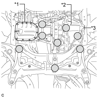
  1. Set the engine lifter.
    Text in Illustration 
    *1
    No. 2 Oil Pan Sub-assembly
    *2
    Drain Plug
    *3
    Rear Cover Plug
    V100145
    Attachment Installation Position

    NOTICE:
    1. Place the height adjustment attachment and plate lift attachment so that the engine assembly with transaxle is level.
    2. Securely support the engine assembly to prevent it from turning upside down until it is secured to an engine stand.
    3. To prevent the No. 2 oil pan sub-assembly from deforming, do not place any attachments onto the No. 2 oil pan sub-assembly of the engine assembly.
    4. Do not place any attachments onto the drain plug and rear cover plug of the hybrid vehicle transaxle assembly.


    A270109
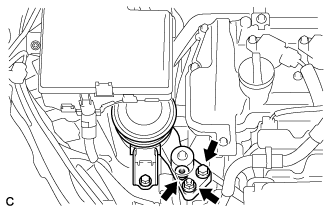
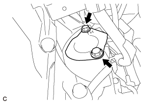
  1. Remove the bolt and 2 nuts, and separate the engine mounting insulator sub-assembly RH from the engine assembly.


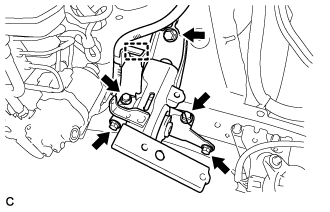
    A268011
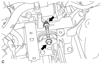
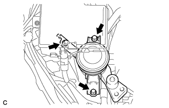
  1. Remove the bolt and nut, and separate the engine mounting insulator LH from the engine mounting bracket LH.


    A268012
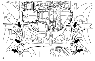
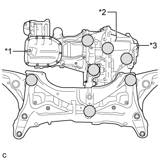
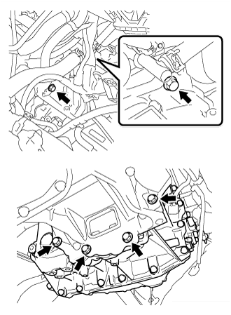
  1. Remove the 6 bolts, operate the engine lifter and slowly remove the engine assembly with transaxle and front suspension crossmember sub-assembly from the vehicle.

    NOTICE:
    Make sure that the engine is clear of all wiring and hoses.


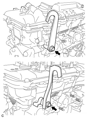
46. INSTALL NO. 1 ENGINE HANGER


    A214905
  1. Install the 2 No. 1 engine hangers with 2 new bolts.

    Torque:
    44 N*m{ 448 kgf*cm , 32 ft.*lbf }

    Part Name
    Part No.
    No. 1 engine hanger
    12281-21090
    Bolt
    91672-81025


47. FIX ENGINE ASSEMBLY WITH TRANSAXLE
  1. Attach the sling device to the engine hangers and chain block.

    NOTICE:
    Make sure that the sling angle is correct to prevent the engine assembly and engine hangers from being damaged or deformed.


    A268014E01
  1. To enable removal of the engine assembly, adjust the positions of the height adjustment attachment and plate lift attachment and set them in place.
    Text in Illustration 
    *1
    No. 2 Oil Pan Sub-assembly
    *2
    Drain Plug
    *3
    Rear Cover Plug
    V100145
    Attachment Installation Position

    NOTICE:
    1. Place the height adjustment attachment and plate lift attachment so that the engine assembly with transaxle is level.
    2. Securely support the engine assembly to prevent it from turning upside down until it is secured to an engine stand.
    3. To prevent the No. 2 oil pan sub-assembly from deforming, do not place any attachments onto the No. 2 oil pan sub-assembly of the engine assembly.
    4. Do not place any attachments onto the drain plug and rear cover plug of the hybrid vehicle transaxle assembly.


    A269294
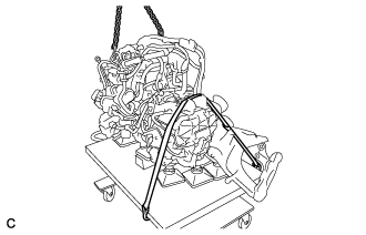
  1. Using a rope or belt, secure the engine assembly with transaxle to the engine lifter.

    NOTICE:
    1. Set the engine assembly with transaxle so that it is horizontal.
    2. Do not tighten the rope or belt with a tightening mechanism or any more than is necessary.


48. REMOVE ENGINE ASSEMBLY


    C249812
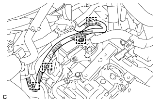
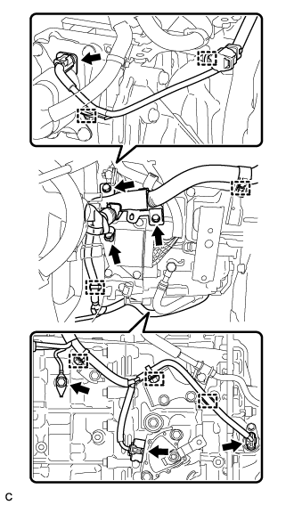
  1. Disconnect the 4 clamps and No. 2 engine wire.


    C249808
  1. Remove the 3 bolts and disconnect the 4 connectors, 7 clamps and wire harness from the hybrid vehicle transaxle assembly.


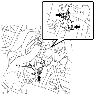
    C249795E01
  1. Remove the 3 bolts, 2 wire harness clamp brackets and transmission control cable clamp from the hybrid vehicle transaxle assembly.
    Text in Illustration 
    *1
    Wire Harness Clamp Bracket
    *2
    Transmission Control Cable Clamp


    C249797
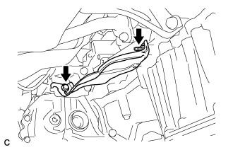
  1. Remove the bolt, nut and drive shaft heat insulator sub-assembly from the engine and drive shaft heat insulator bracket.


    C249798
  1. Disconnect the clamp from the drive shaft heat insulator bracket.

  1. Remove the 2 bolts and drive shaft heat insulator bracket from the engine.


    C249799
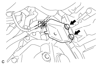
  1. Remove the 2 bolts and starter hole heat insulator from the engine.


    C251104
  1. Disengage the claw and remove the flywheel housing side cover from the engine.


    C250720
  1. Remove the 6 bolts and hybrid vehicle transaxle assembly.

    NOTICE:
    1. To avoid damage to the knock pins, do not pry between the hybrid vehicle transaxle assembly and the engine.
    2. To prevent the splines of the damper from becoming misaligned, do not allow the transaxle to hit the damper during transaxle removal and installation.


49. REMOVE TRANSMISSION INPUT DAMPER ASSEMBLY
  1. Gently place the engine assembly onto wood blocks or equivalent.

    NOTICE:
    1. Set the engine assembly so that it is horizontal.
    2. To prevent the No. 2 oil pan sub-assembly from deforming, do not place any attachments onto the No. 2 oil pan sub-assembly of the engine assembly.
    3. This step should be done while hanging the engine assembly using the sling device and chain block.

  1. Remove the transmission input damper assembly .


50. REMOVE FLYWHEEL SUB-ASSEMBLY
  1. Gently place the engine assembly onto wood blocks or equivalent.

    NOTICE:
    1. Set the engine assembly so that it is horizontal.
    2. To prevent the No. 2 oil pan sub-assembly from deforming, do not place any attachments onto the No. 2 oil pan sub-assembly of the engine assembly.
    3. This step should be done while hanging the engine assembly using the sling device and chain block.

  1. Remove the flywheel sub-assembly .


51. REMOVE ENGINE MOUNTING INSULATOR SUB-ASSEMBLY RH

HINT:
Perform this procedure only when replacement of the engine mounting insulator sub-assembly RH is necessary.


    A270110
  1. Remove the 3 bolts and engine mounting insulator sub-assembly RH.


52. REMOVE ENGINE MOUNTING INSULATOR LH

HINT:
Perform this procedure only when replacement of the engine mounting insulator LH is necessary.


    A268018
  1. Disconnect the wire harness clamp.

  1. Remove the 5 bolts and engine mounting insulator LH.


53. INSTALL ENGINE STAND
  1. Using a sling device and chain block, install the engine stand to the engine assembly.

    NOTICE:
    1. Make sure that the sling angle is correct to prevent the engine assembly and engine hangers from being damaged or deformed.
    2. Securely support the engine assembly to prevent it from turning upside down until it is secured to an engine stand.


54. DISCONNECT ENGINE WIRE
  1. Disconnect all of the clamps and connectors and remove the engine wire from the engine assembly.


55. REMOVE NO. 1 ENGINE HANGER
  1. Remove the 2 bolts and 2 No. 1 engine hangers.