BRAKE CONTROL / DYNAMIC CONTROL SYSTEMS BRAKE PEDAL STROKE SENSOR(for LHD) REMOVAL
CAUTION / NOTICE / HINT
The necessary procedures (adjustment, calibration, initialization, or registration) that must be performed after parts are removed, installed, or replaced during brake pedal stroke sensor assembly removal/installation are shown below.
| Replaced Part or Performed Procedure | Necessary Procedure | Effect/Inoperative Function when Necessary Procedure not Performed | Link |
|---|---|---|---|
| Auxiliary battery terminal is disconnected/reconnected | Memorize steering angle neutral point | Lane departure alert system (w/ Steering Control) | ( ) |
| Intelligent clearance sonar system | |||
| Simple intelligent parking assist system | |||
| Pre-crash safety system | |||
| Parking assist monitor system | ()
|
||
| Initialize back door lock | Power door lock control system | ()
|
|
| Replacement of brake pedal stroke sensor assembly | 1.
Clear the data stored during previous linear solenoid valve offset learning, ABS holding solenoid valve learning, brake pedal stroke sensor assembly zero point calibration and system information memorization. 2.
Perform linear solenoid valve offset learning, ABS holding solenoid valve learning, brake pedal stroke sensor assembly zero point calibration and system information memorization. |
·
DTCs are stored ·
ABS warning light illuminates ·
Brake warning light/yellow (minor malfunction) illuminates ·
Slip indicator light illuminates ·
VSC disabled or malfunctions |
()for Initialization
( )for Calibration
|
CAUTION / NOTICE / HINT
- NOTICE:
-
While the auxiliary battery is connected, even if the power switch is off, the brake control system activates when the brake pedal is depressed or any door courtesy switch turns on. Therefore, when servicing the brake system components, do not operate the brake pedal or open/close the doors while the auxiliary battery is connected.
PROCEDURE

 1. PRECAUTION
- NOTICE:
-
After turning the power switch off, waiting time may be required before disconnecting the cable from the negative (-) auxiliary battery terminal. Therefore, make sure to read the disconnecting the cable from the negative (-) auxiliary battery terminal notices before proceeding with work.
-
Click hereGeneral>INTRODUCTION>REPAIR INSTRUCTION>PRECAUTION
2.DISCONNECT CABLE FROM NEGATIVE AUXILIARY BATTERY TERMINAL
67914
3.REMOVE FRONT DOOR SCUFF PLATE LH
62112
4.REMOVE COWL SIDE TRIM BOARD LH
55606
5.REMOVE NO. 1 INSTRUMENT PANEL UNDER COVER SUB-ASSEMBLY
55436A
6.REMOVE INSTRUMENT PANEL FINISH PANEL END LH
55470
7.REMOVE INSTRUMENT CLUSTER FINISH PANEL GARNISH ASSEMBLY
53601
8.DISCONNECT HOOD LOCK CONTROL LEVER SUB-ASSEMBLY
55480D
9.REMOVE LOWER INSTRUMENT PANEL FINISH PANEL ASSEMBLY
89510D
10.REMOVE BRAKE PEDAL STROKE SENSOR ASSEMBLY
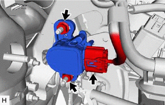
Disconnect the connector from the brake pedal stroke sensor assembly.
Remove the 2 nuts and brake pedal stroke sensor assembly from the brake pedal support assembly.
- NOTICE:
- ·
Do not drop the brake pedal stroke sensor assembly.
·If the brake pedal stroke sensor assembly has been dropped, replace the brake pedal stroke sensor assembly with a new one.