P610 HYBRID TRANSMISSION / TRANSAXLE OIL COOLER INSTALLATION
PROCEDURE

 1.INSTALL NO. 1 MOTOR COOLING HOSE
- HINT:
-
Perform this procedure only when replacement of the motor cooling cooler is necessary.
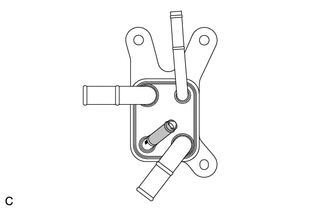

|
ATF Application Area |
Coat a small amount of ATF as shown in the illustration.
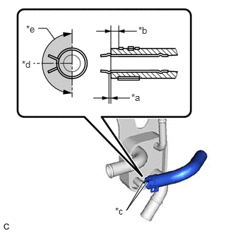
| *a | 0 to 3 mm (0 to 0.118 in.) |
| *b | 2 to 7 mm (0.0787 to 0.276 in.) |
| *c | Paint Mark |
| *d | Center of Paint Mark |
| *e | 180° |
|
|
Clip Location |
Install the No. 1 motor cooling hose to the motor cooling cooler and slide the clip to secure it.
- NOTICE:
- ·
Be careful not to deform the motor cooling cooler.
·Make sure to align the paint mark on the No. 1 motor cooling hose with the paint mark on the motor cooling cooler.
·Make sure that the claws of the clip are positioned within the area shown in the illustration.
2.INSTALL NO. 2 MOTOR COOLING HOSE
- HINT:
-
Perform this procedure only when replacement of the motor cooling cooler is necessary.
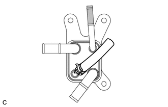
|
|
ATF Application Area |
Coat a small amount of ATF as shown in the illustration.
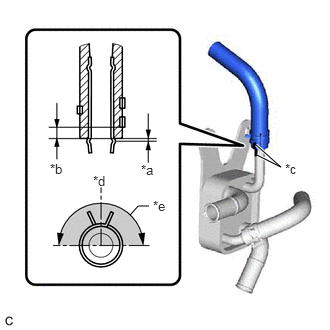
| *a | 0 to 3 mm (0 to 0.118 in.) |
| *b | 2 to 7 mm (0.0787 to 0.276 in.) |
| *c | Paint Mark |
| *d | Center of Paint Mark |
| *e | 180° |
|
|
Clip Location |
Install the No. 2 motor cooling hose to the motor cooling cooler and slide the clip to secure it.
- NOTICE:
- ·
Be careful not to deform the motor cooling cooler.
·Make sure to align the paint mark on the No. 2 motor cooling hose with the paint mark on the motor cooling cooler.
·Make sure that the claws of the clip are positioned within the area shown in the illustration.
G125A
3.INSTALL MOTOR COOLING COOLER
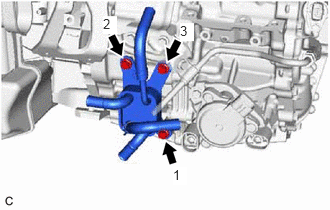
Temporarily install the motor cooling cooler to the hybrid vehicle transaxle assembly with the 3 bolts.
Tighten the 3 bolts in the order shown in the illustration.
- Torque:
- 11.5 N*m (117 kgf*cm, 8 ft.*lbf)
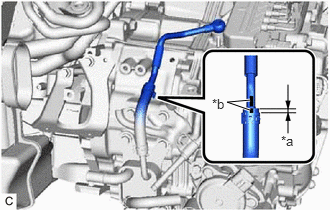
| *a | 2 to 7 mm (0.0787 to 0.276 in.) |
| *b | Paint Mark |
Install the No. 2 motor cooling pipe to the No. 2 motor cooling hose and slide the clip to secure it.
- NOTICE:
-
Make sure to align the paint mark on the No. 2 motor cooling pipe with the paint mark on the No. 2 motor cooling hose.
Temporarily install the No. 2 motor cooling pipe to the hybrid vehicle transaxle assembly with the union bolt and a new gasket.
Install the No. 1 oil cooler tube clamp to the hose bracket with the bolt.
- Torque:
- 11.5 N*m (117 kgf*cm, 8 ft.*lbf)
Tighten the union bolt to install the No. 2 motor cooling pipe.
- Torque:
- 35 N*m (357 kgf*cm, 26 ft.*lbf)
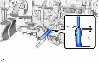
| *a | 2 to 7 mm (0.0787 to 0.276 in.) |
| *b | Paint Mark |
Connect the No. 1 motor cooling hose to the No. 1 motor cooling pipe and slide the clip to secure it.
- NOTICE:
-
Make sure to align the paint mark on the No. 1 motor cooling pipe with the paint mark on the No. 1 motor cooling hose.
G922F
4.CONNECT OUTLET NO. 1 HYBRID WATER PUMP HOSE
G922H
5.CONNECT INLET HYBRID RADIATOR HOSE
17701
6.INSTALL AIR CLEANER CASE SUB-ASSEMBLY
17801
7.INSTALL AIR CLEANER FILTER ELEMENT SUB-ASSEMBLY
17705
8.INSTALL AIR CLEANER CAP SUB-ASSEMBLY
G9200
9.INSTALL INVERTER WITH CONVERTER ASSEMBLY
10.INSPECT HYBRID TRANSAXLE FLUID
11.INSPECT FOR HYBRID TRANSAXLE FLUID LEAK
51444C
12.INSTALL REAR MOTOR UNDER COVER LH
51441
13.INSTALL NO. 1 ENGINE UNDER COVER