C2121/21 No Signal from Transmitter ID1 in Main Mode
Diagnostic trouble codes · Vehicles built from Nov 2005
Also covers:
- C2122/22 No Signal from Transmitter ID2 in Main Mode
- C2123/23 No Signal from Transmitter ID3 in Main Mode
- C2124/24 No Signal from Transmitter ID4 in Main Mode
- C2181/81 Transmitter ID1 not Received (Test Mode DTC)
- C2182/82 Transmitter ID2 not Received (Test Mode DTC)
- C2183/83 Transmitter ID3 not Received (Test Mode DTC)
- C2184/84 Transmitter ID4 not Received (Test Mode DTC)
DESCRIPTION
The tire pressure warning valve and transmitter constantly sends radio waves to the tire pressure warning ECU and receiver.Under the following conditions, the tire pressure warning antenna and receiver is unable to receiver the signals from the tire pressure warning valve and transmitter, and DTC is output.
- Areas facilities, or devices that use similar radio frequencies are located in the vicinity of the vehicle.
- Devices using similar radio frequencies are used in the vehicle.
| DTC No. |
DTC Detection Condition |
Trouble Area |
| C2121/21 C2122/22 C2123/23 C2124/24 |
These DTCs are detected when no signals are received for 51 minutes or more, after a vehicle speed of 5 mph (8 km/h) or more is detected and no signals are received for 12 minutes or more |
|
| C2181/81 C2182/82 C2183/83 C2184/84 |
Malfunction in transmission / reception circuit |
|
- HINT:
- When no signal are received for 60 minutes or more, a DTC is output.
- It is necessary to perform the procedure to identify the tire pressure warning valve and transmitter that is malfunctioning because it cannot be identified by the output DTC.
WIRING DIAGRAM
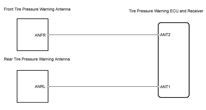

INSPECTION PROCEDURE
- NOTICE:
- It is necessary to register an ID code after replacing the tire wheel and/or the tire pressure warning ECU and receiver (Click here).
| 1. IDENTIFY TRANSMITTER (CORRESPONDING TO DTC) |

Set the pressure of each tire to the specified value.
- Standard pressure:
- 220 kPa (2.2 kgf/cm2, 32 psi)
Connect the intelligent tester to the DLC3.
Select tirepress by following the prompts displayed on the intelligent tester.
- Tire pressure warning ECU and receiver:
Item
Measurement Item / Range (Display)
Normal Condition
Diagnostic Note
Tirepress1
ID1 tire pressure/ minimum: 0 kPa (0 kgf/cm2, 0 psi) maximum: 637.5 kPa (6.5 kgf/cm2, 92.5 psi)
Actual tire pressure
-
Tirepress2
ID2 tire pressure/ minimum: 0 kPa (0 kgf/cm2, 0 psi) maximum: 637.5 kPa (6.5 kgf/cm2, 92.5 psi)
Actual tire pressure
-
Tirepress3
ID3 tire pressure/ minimum: 0 kPa (0 kgf/cm2, 0 psi) maximum: 637.5 kPa (6.5 kgf/cm2, 92.5 psi)
Actual tire pressure
-
Tirepress4
ID4 tire pressure/ minimum: 0 kPa (0 kgf/cm2, 0 psi) maximum: 637.5 kPa (6.5 kgf/cm2, 92.5 psi)
Actual tire pressure
-
Rapidly release the tire pressure from any tire by 40 kPa (0.4 kgf/cm2, 5.8 psi) for 30 seconds or more.
- HINT:
- Identify the malfunctioning tire pressure warning valve and transmitter by rapidly releasing the pressure from each tire.
- Record which tirepress data (ID1 to ID4) corresponds to each tire.
- Identify the malfunctioning tire pressure warning valve and transmitter by rapidly releasing the pressure from each tire.
Check the Data List.
- Result:
Condition
Detection Condition
One of tirepress data (ID1 to ID4) changed
Normal
No tirepress data changed
Transmitter corresponding to DTC
- NOTICE:
- It may take up to 1 minute to display the updated tire pressure data.
- When the tirepress data (IDs 1 to 4) changes, reset the tire pressure of the tires to the specified value, rotate the tires 90 to 270° and recheck.
- When the transmitter is normal, record the tire location and the transmitter ID.
- It may take up to 1 minute to display the updated tire pressure data.
When one of the tirepress data (IDs 1 to 4) changes, repeat the same procedure on the rest of the tires (one by one) to identify which tire pressure warning valve and transmitter the DTC corresponds to. Set the tire pressures to the appropriate specified values.
Set the pressure of each tire to the specified value.
- Standard pressure:
- 220 kPa (2.2 kgf/cm2, 32 psi)
Check all transmitters of the tires.
- Result:
Result
Detection Condition
One or more of transmitters abnormal
All abnormal
A
All normal
B
|
|
||||

| A | |
 |
| 2. CHECK WIRE HARNESS (ECU - ANTENNA) |
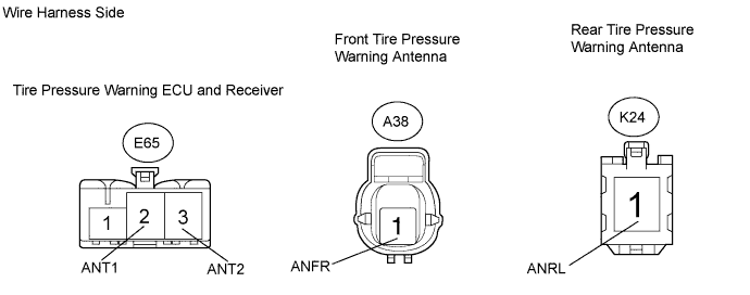
Disconnect the E65 ECU connector.
Disconnect the A38*1 and K24*2 antenna connector.
- HINT:
- *1: Front
- *2: Rear
Measure the resistance of the wire harness side connectors.
- Standard resistance:
Front Tester Connection
Specified Condition
E65-3 (ANT2) - A38-1 (ANFR)
Below 1 Ω
- Rear:
Tester Connection
Specified Condition
E65-2 (ANT1) - K24-1 (ANRL)
Below 1 Ω
|
|
||||
| OK | |
|
| 3. READ VALUE USING INTELLIGENT TESTER (TIRE PRESSURE) |
Check the Data List tire pressure valve.
- Tire pressure warning ECU and receiver:
Item
Measurement Item / Range (Display)
Normal Condition
Diagnostic Note
Tirepress1
ID1 tire pressure/ minimum: 0 kPa (0 kgf/cm2, 0 psi) maximum: 637.5 kPa (6.5 kgf/cm2, 92.5 psi)
Actual tire pressure
-
Tirepress2
ID2 tire pressure/ minimum: 0 kPa (0 kgf/cm2, 0 psi) maximum: 637.5 kPa (6.5 kgf/cm2, 92.5 psi)
Actual tire pressure
-
Tirepress3
ID3 tire pressure/ minimum: 0 kPa (0 kgf/cm2, 0 psi) maximum: 637.5 kPa (6.5 kgf/cm2, 92.5 psi)
Actual tire pressure
-
Tirepress4
ID4 tire pressure/ minimum: 0 kPa (0 kgf/cm2, 0 psi) maximum: 637.5 kPa (6.5 kgf/cm2, 92.5 psi)
Actual tire pressure
-
- OK:
- All tire pressure readings are equal to the actual tire pressure.
- NOTICE:
- It may take up to 1 minute to display the updated tire pressure data.
|
|
||||
| OK | ||
 |
||
| ||