DISASSEMBLY
Removal / installation · Vehicles built from Nov 2005
| 1. DISCONNECT CABLE FROM NEGATIVE BATTERY TERMINAL |

- CAUTION:
- Wait at least 90 seconds after disconnecting the cable from the negative (-) battery terminal to prevent airbag and seat belt pretensioner activation.
| 2. REMOVE BACK DOOR CENTER GARNISH |
Using a screwdriver, detach the 4 claws and 4 clips and remove the garnish.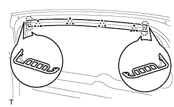

- HINT:
- Tape the screwdriver tip before use.
| 3. REMOVE BACK DOOR SIDE GARNISH LH |
Using a screwdriver, detach the 2 claws and 2 clips and remove the garnish.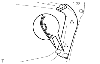
| 4. REMOVE BACK DOOR SIDE GARNISH RH |
- HINT:
- Use the same procedures described for the LH side.
| 5. REMOVE BACK DOOR COURTESY LIGHT ASSEMBLY |
Using a screwdriver, pry out the light as shown in the illustration.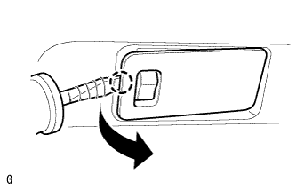
- HINT:
- Tape the screwdriver tip before use.
Detach the 4 claws and remove the light shade.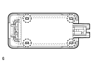
Remove the light bulb from the light.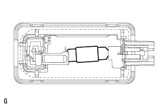
| 6. REMOVE BACK DOOR TRIM BOARD |
Using a screwdriver, detach the 13 clips and remove the trim board.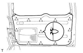
- HINT:
- Tape the screwdriver tip before use.
- If the screwdriver cannot reach the clips, pull on the lower trim to remove it.
- Tape the screwdriver tip before use.
Remove the 5 screws and the back door trim pocket.
| 7. REMOVE REAR WIPER ARM AND BLADE ASSEMBLY |
Widen each end of the cap 5 mm (0.19in).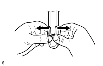
Lift the both widened ends of the cap.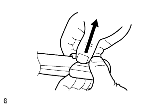
Rotate the cap. Fix the cap in place.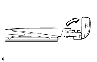
Remove the nut and arm and blade.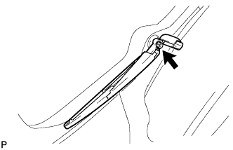
| 8. REMOVE REAR SPOILER |
Remove the 3 bolts.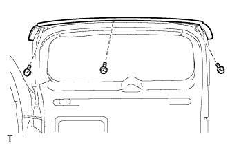
Remove the 3 clips and spoiler.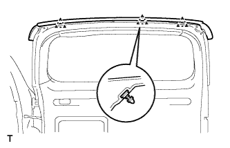
Disconnect the center stop light connector and remove the rear spoiler.
| 9. REMOVE CENTER STOP LIGHT ASSEMBLY |
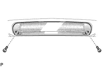 |
Disconnect the connector.
Remove the 2 screws and center stop light.
| 10. REMOVE SPARE WHEEL CARRIER BRACKET SUB-ASSEMBLY (w/ Tire Carrier) |
w/o Breakaway Bolt:
Remove the spare wheel carrier bracket.
Remove the 4 bolts.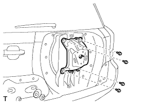
Detach the 2 clips and remove the carrier bracket.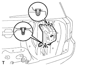
w/ Breakaway Bolt: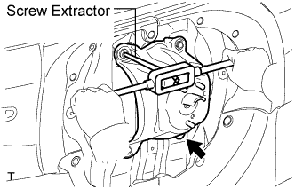
Remove the spare wheel carrier bracket.Using a centering punch, mark the center of the 2 breakaway bolts.
Using a 3 to 4 mm (0.12 to 0.16 in.) drill, drill a hole in the 2 breakaway bolts heads.
Using a screw extractor, remove the 2 breakaway bolts.
Remove the 2 bolts.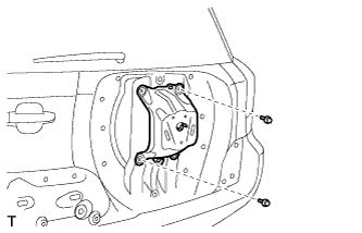
Detach the 2 clips and remove the carrier bracket.
| 11. REMOVE LOWER BACK DOOR OUTSIDE GARNISH SUB-ASSEMBLY LH |
Remove the screw and 8 clips.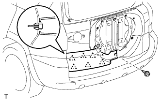
Remove the back door outside garnish.
| 12. REMOVE LOWER BACK DOOR OUTSIDE GARNISH SUB-ASSEMBLY LH (w/ License Plate Light) |
Remove the screw and 7 clips.
Remove the back door outside garnish and disconnect the connector.
for 1 piece type:
Remove the 1 piece type license plate light (Click here).
for 2 piece type:
Remove the 2 piece type license plate lights (Click here).
| 13. REMOVE LOWER BACK DOOR OUTSIDE GARNISH SUB-ASSEMBLY LH (w/ Rear Fog Light) |
Remove the screw and 8 clips.
Remove the back door outside garnish and disconnect the connector.
Remove the rear fog light (Click here).
| 14. REMOVE UPPER BACK DOOR OUTSIDE GARNISH SUB-ASSEMBLY LH |
Remove the screw and 6 clips.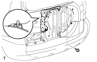
Remove the back door outside garnish.
| 15. REMOVE LOWER BACK DOOR OUTSIDE GARNISH SUB-ASSEMBLY RH |
Remove the 5 clips and detach the claw.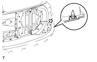
Remove the back door outside garnish.
| 16. REMOVE UPPER BACK DOOR OUTSIDE GARNISH SUB-ASSEMBLY RH |
Remove the 6 clips and back door outside garnish.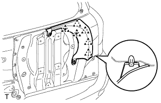
| 17. REMOVE BACK DOOR OUTSIDE GARNISH SUB-ASSEMBLY (w/o Tire Carrier) |
Remove the 3 nuts 6 clips.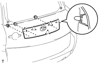
Disconnect the connector and remove the back door outside garnish.
Remove the 2 license plate lights (Click here).
| 18. REMOVE TELEVISION CAMERA ASSEMBLY (w/ Parking Assist Monitor System) |
Disconnect the television camera connector and detach the clamp.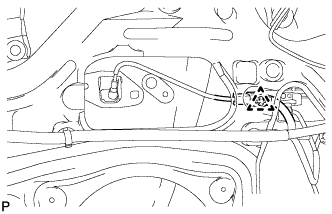
Remove the screw and television camera.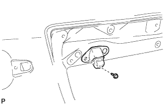
| 19. REMOVE LOWER BACK DOOR OUTSIDE GARNISH SUB-ASSEMBLY (w/o Tire Carrier) |
Remove 15 clips and detach the claws.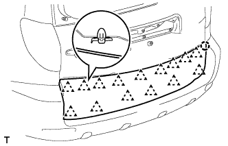
Remove the back door outside garnish.
| 20. REMOVE BACK DOOR OUTSIDE GARNISH CLIP |
Remove the 2 screws and 2 clips.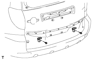
| 21. REMOVE REAR WIPER MOTOR ASSEMBLY |
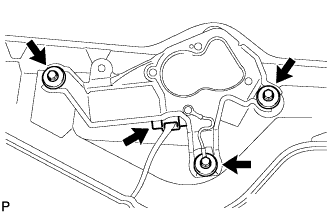 |
Disconnect the connector.
Remove the 3 bolts and wiper motor.
| 22. REMOVE BACK DOOR SERVICE HOLE COVER |
Disconnect each connector and remove the service hole cover.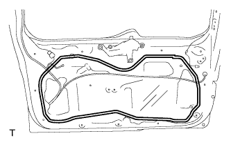
- HINT:
- Remove the remaining tape on the door.
| 23. REMOVE BACK DOOR LOCK ASSEMBLY |
Disconnect the connector.
Using a T30 "torx" socket, remove the 3 screws.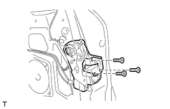
- NOTICE:
- Be careful when removing the bolts as the door lock may fall and become damaged.
Slide the door lock downward to disconnect the back door lock open rod from the door lock. Then remove the door lock.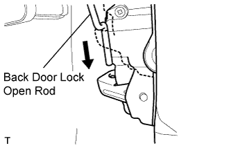
- HINT:
- Remove the door lock through the service hole.
| 24. REMOVE BACK DOOR OUTSIDE HANDLE COVER |
Remove the hole plug.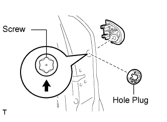
Using a T30 "torx" socket, loosen the screw and remove the cover.
- HINT:
- Loosen but do not remove the screw.
| 25. REMOVE BACK DOOR OUTSIDE HANDLE |
w/ Entry and Start System:
Disconnect the connector.
Remove the handle by sliding and pulling it in the direction indicated by the arrow in the illustration.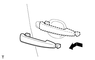
| 26. REMOVE BACK DOOR OUTSIDE HANDLE FRAME SUB-ASSEMBLY |
w/ Entry and Start System: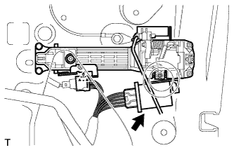
Disconnect the connector and clamp.
Using a T30 "torx" socket, loosen the screw of the frame.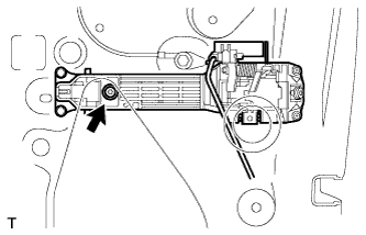
- HINT:
- Loosen but do not remove the screw.
Using pliers, pinch the clip.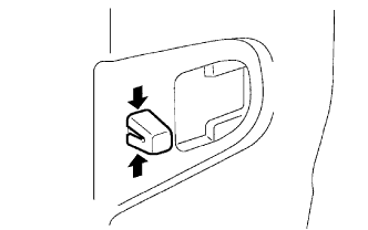
- NOTICE:
- Be sure to remove the outside handle frame together with the clip, as the clip will be damaged if it remains attached to the door panel.
Detach the claw and remove the frame.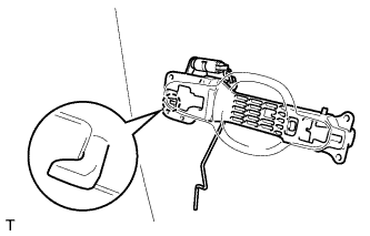
- HINT:
- Remove the frame through the service hole.
Remove the front door lock open rod.
| 27. REMOVE BACK DOOR OUTSIDE HANDLE FRONT PAD |
Detach the 2 claws and remove the pad.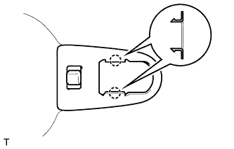
| 28. REMOVE BACK DOOR OUTSIDE HANDLE REAR PAD |
Detach the 2 claws and remove the pad.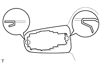
| 29. REMOVE BACK DOOR CHECK ASSEMBLY |
Remove the bolt, 2 nuts and door check.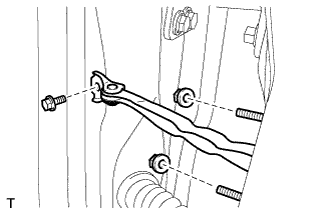
- HINT:
- Remove the door check through the service hole.
| 30. REMOVE BACK DOOR SIDE FEMALE STOPPER |
Remove the 2 bolts and stopper.
| 31. REMOVE CUSHION |
Remove the 2 cushions.
| 32. REMOVE STOPPER |