REMOVAL
Removal / installation · Vehicles built Jan 2007 – Jul 2007
Versions by build date: Nov 2005 – Dec 2006 Jan 2007 – Jul 2007 Aug 2007 – Jul 2008 from Aug 2008
- HINT:
- Use the same procedures for the LH side and RH side.
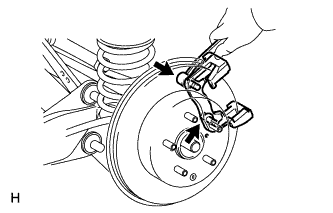
- The procedures listed below are for the LH side.
| 1.
DISCONNECT CABLE FROM NEGATIVE BATTERY TERMINAL |
 |
- CAUTION:
- Wait at least 90 seconds after disconnecting the cable from the negative (-) battery terminal to prevent airbag and seat belt pretensioner activation.
| 3.
REMOVE DECK TRIM SIDE PANEL ASSEMBLY LH |
|
Remove the deck trim side panel LH (Click here).
- HINT:
- Refer to the procedures from the removal of the rear door scuff plate LH up until the removal of the deck trim side panel LH.
| 4.
REMOVE SKID CONTROL SENSOR WIRE |
|
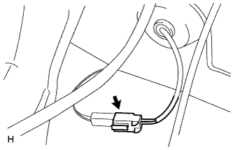
- Disconnect the skid control sensor wire connector.
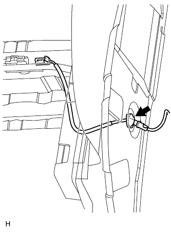
- Disconnect the grommet of the skid control sensor wire from the hole of the wheel house.
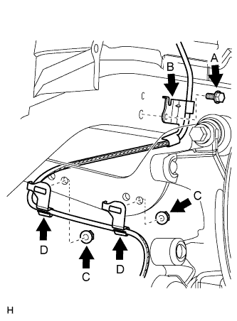
- Remove the bolt (labeled A) and sensor clamp (labeled B) from the side member.
Remove the 2 nuts (labeled C) and sensor clamps (labeled D) from the upper arm.
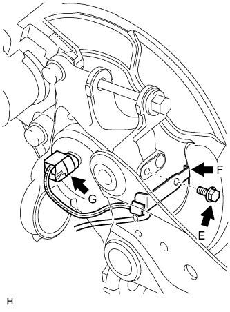
- Remove the bolt (labeled E) and sensor clamp (labeled F) from the carrier.
Disconnect the skid control sensor wire connector (labeled G) from the speed sensor.
| 5.
REMOVE REAR DISC BRAKE CYLINDER MOUNTING LH
|
|
- Remove the 2 bolts and cylinder mounting.
| 6.
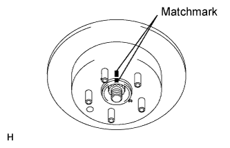
REMOVE REAR DISC
|
|
- Put matchmarks on the disc and axle hub.
Release the parking brake.
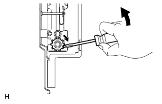
- Turn the shoe adjuster until the disc turns freely, and then remove the disc.
Install the shoe adjusting hole plug to the rear disc.
| 7.
REMOVE REAR AXLE HUB AND BEARING ASSEMBLY LH |
|
Remove the rear axle hub and bearing LH (Click here).
| 8.
REMOVE SKID CONTROL SENSOR LH |
|
Mount the front axle hub in a soft jaw vise.
- NOTICE:
- Replace the hub and bearing if it is dropped or receives a strong shock.
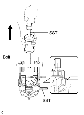
Using a pin punch and hammer, tap out the 2 pins and remove the 2 attachments from SST.
- Using SST and the 2 bolts (diameter: 12 mm; pitch: 1.
- SST
- 09520-00031
(09520-00040)
09521-00020
09950-00020
- NOTICE:
- If the sensor rotor is damaged, replace the axle hub.
- Do not scratch the contacting surface of the hub and bearing and skid control sensor.