INSTALLATION
Removal / installation · Vehicles built from Aug 2007
Versions by build date: Nov 2005 – Dec 2006 Jan 2007 – Jul 2007 from Aug 2007
| 1. INSTALL REAR DIFFERENTIAL SIDE GEAR SHAFT OIL SEAL |

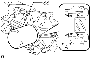  |
Apply a light coat of MP grease to the lip of a new rear differential side gear shaft oil seal.
Using SST and a hammer, tap the 2 rear differential side gear shaft oil seals into the rear differential carrier and differential side bearing retainer according to the specification.
- SST
- 09223-00010
- Standard oil seal tapping amount (A value):
- 7.2 +-0.5 mm (0.28 +-0.02 in.)
| 2. INSTALL DIFFERENTIAL CARRIER ASSEMBLY |
Support the rear differential carrier with a transmission jack or equivalent.
Apply hypoid gear oil to the splines of the left and right rear drive shaft inboard joints.
Align the splines of the rear drive shaft inboard joints and, using a brass bar and hammer, tap in the left and right rear drive shafts.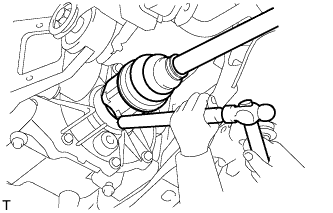
- NOTICE:
- Face the cutout section of the snap ring downward.
- Do not damage the oil seal during the insertion.
- Do not strike the tip of the outboard joint with the hammer.
- Face the cutout section of the snap ring downward.
- HINT:
- Determine whether or not the rear drive shaft is completely tapped in by checking for changes in sound or the reaction force of the brass bar.
Slowly raise the transmission jack, install the 3 bolts.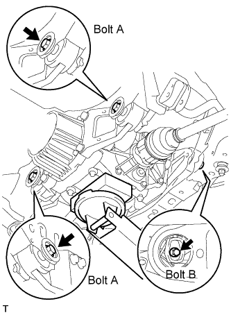
- Torque:
- 86 N*m{ 877 kgf*cm , 63 ft.*lbf } for bolt A
- 140 N*m{ 1,428 kgf*cm , 103 ft.*lbf } for bolt B
- NOTICE:
- Tighten the bolts, not the nuts.
Connect the connector.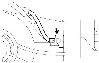
Install the breather tube.
Connect the harness clamp.
| 3. TEMPORARILY INSTALL PROPELLER WITH CENTER BEARING SHAFT ASSEMBLY |
Align the matchmarks of the transfer and propeller shaft.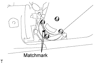
Temporarily install the propeller shaft with center bearing with the 4 nuts and 4 washers.
Align the matchmarks of the differential carrier and propeller shaft.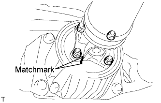
Temporarily install the propeller shaft with center bearing with the 4 bolts and 4 washers.
Temporarily install the center support bearing and center support bearing washer with the 2 bolts.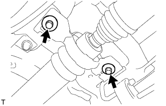
| 4. TIGHTEN PROPELLER WITH CENTER BEARING SHAFT ASSEMBLY |
Tighten the 4 nuts of the propeller shaft and transfer to the torque specification.
- Torque:
- 35 N*m{ 357 kgf*cm , 26 ft.*lbf }
Tighten the 4 nuts of the propeller shaft and differential carrier to the torque specification.
- Torque:
- 35 N*m{ 357 kgf*cm , 26 ft.*lbf }
Check that the center line of the center support bearing housing is perpendicular to the axis of the propeller shaft.
Tighten the 2 bolts of the center support bearing to the torque specification.
- Torque:
- 36.8 N*m{ 375 kgf*cm , 27 ft.*lbf }
| 5. INSPECT AND ADJUST JOINT ANGLE |
- NOTICE:
- Perform the measurement with a 4 post lift or pit so that the vehicle is supported by all 4 wheels as if it were on the ground.
Before the angle measurement, stabilize each part by performing procedures like those described below.
Rotate the propeller shaft several times by hand.
Set the jack to the differential, and raise and lower the differential.
Using SST and a straightedge, measure the angle of the transfer flange (angle D) and the angle of the intermediate shaft (angle A).
- SST
- 09370-50010
- NOTICE:
- Make sure the straightedge and SST are at a right angle.
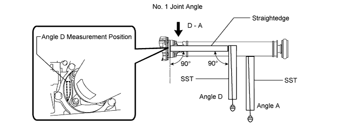
Subtract the measured angle of the intermediate shaft (angle A) from the measured angle of the transfer flange (angle D) to obtain the No. 1 joint angle.
- No. 1 Joint Angle:
Measurement Position
No. 1 Joint Angle
D - A
2°27' +/-60'
Using SST, measure the angle of the intermediate shaft (angle A) and the angle of the propeller shaft (angle B).
- SST
- 09370-50010
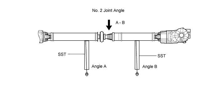
Subtract the measured angle of the propeller shaft (angle B) from the measured angle of the intermediate shaft (angle A) to obtain the No. 2 joint angle.
- No. 2 Joint Angle:
Measurement Position
Engine
Transmission
No. 2 Joint Angle
A - B
1AZ-FE
A/T
1°29' +/-1°30'
M/T
1°28' +/-1°30'
2AZ-FE
A/T
1°35' +/-1°30'
M/T
1°34' +/-1°30'
2GR-FE
A/T
1°35' +/-1°30'
2AD-FTV
2AD-FHV
M/T
1°28' +/-1°30'
Using SST, measure the angle of the propeller shaft (angle B) and the angle of the rear differential (angle C).
- SST
- 09370-50010
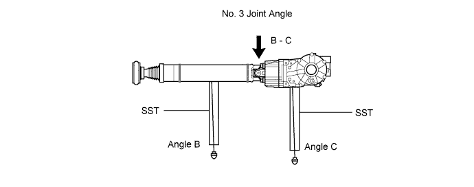
Subtract the measured angle of the propeller shaft (angle B) from the measured angle of the rear differential (angle C) to obtain the No. 3 joint angle.
- No. 3 Joint Angle:
Measurement Position
Engine
Transmission
No. 3 Joint Angle
B - C
1AZ-FE
A/T
2°10' +/-60'
M/T
2°11' +/-60'
2AZ-FE
A/T
2°04' +/-60'
M/T
2GR-FE
A/T
2°04' +/-60'
2AD-FTV
2AD-FHV
M/T
2°10' +/-60'
| 6. INSTALL FRONT EXHAUST PIPE ASSEMBLY |
- HINT:
- 2AD-FTV: (Click here for CCO, Click here for DPF).
- 2AD-FHV: (Click here).
- 2AD-FTV: (Click here for CCO, Click here for DPF).
| 7. INSTALL CENTER EXHAUST PIPE ASSEMBLY |
- HINT:
- 1AZ-FE: (Click here).
- 2AZ-FE: (Click here).
- 2GR-FE: (Click here).
- 1AZ-FE: (Click here).
| 8. INSTALL TAILPIPE ASSEMBLY |
- HINT:
- 1AZ-FE: (Click here).
- 2AD-FT: (Click here for CCO, Click here for DPF).
- 2AD-FHV: (Click here).
- 2AZ-FE: (Click here).
- 2GR-FE: (Click here).
- 1AZ-FE: (Click here).
| 9. ADD DIFFERENTIAL OIL |
Stop the vehicle on a level surface.
Using a 10 mm socket hexagon wrench, remove the rear differential filler plug and gasket.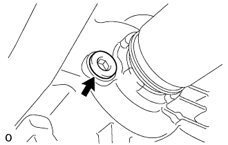
Check that the oil level is between 0 to 5 mm (0 to 0.20 in.) from the bottom lip of the differential filler plug hole.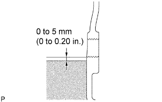
- NOTICE:
- After changing the oil seal, drive the vehicle and then check the oil level again.
- Too much or too little oil will lead to differential problems.
- After changing the oil seal, drive the vehicle and then check the oil level again.
- If there is not enough oil, inspect for oil leaks, and fill the differential carrier assembly with hypoid gear oil.
- Recommended viscosity:
- SAE 90
- Standard oil grade:
- Hypoid gear oil SX API GL-5
- Standard differential oil capacity:
- 0.45 to 0.55 liters (0.48 to 0.58 US qts., 0.40 to 0.48 Imp. qts.)
Using a 10 mm socket hexagon wrench, install a new gasket and the rear differential filler plug.
- Torque:
- 39 N*m{ 398 kgf*cm , 29 ft.*lbf }
| 10. CHECK FOR DIFFERENTIAL OIL LEAKAGE |
| 11. CHECK FOR EXHAUST GAS LEAKAGE |
- If gas is leaking, tighten the areas necessary to stop the leak. Replace damaged parts as necessary.