| B |  |
| Go to step 5 |
| C |  |
| GO TO DTC CHART (Click here) |
DTC P0989 Transmission Fluid Pressure Sensor / Switch "E" Circuit Low |
DTC P0990 Transmission Fluid Pressure Sensor / Switch "E" Circuit High |
| DTC Code | DTC Detection Condition | Trouble Area |
| P0989 | No. 3 ATF pressure switch is off when lock-up occurs in response to a lock-up request (2-trip detection logic). |
|
| P0990 | When both of the following are detected (2-trip detection logic):
|
| DATA LIST |
Warm up the engine.
Turn the ignition switch off.
Connect the intelligent tester to the DLC3.
Turn the ignition switch to ON.
Turn the intelligent tester on.
Enter the following menus: Powertrain / ECT / Data List.
According to the display on the tester, read the Data List.
| Tester Display | Measurement Item/Range | Normal Condition | Diagnostic Note |
| TPS 3 Switch | No. 3 ATF pressure switch status/ ON or OFF |
| - |
| 1.CHECK DTC OUTPUT (IN ADDITION TO DTC P0989 OR P0990) |
Connect the intelligent tester to the DLC3.
Turn the ignition switch to ON.
Turn the intelligent tester on.
Enter the following menus: Powertrain / ECT / DTC.
Read the DTCs using the intelligent tester.
| Result | Proceed to |
| Only P0989 is output | A |
| Only P0990 is output | B |
| P0989 or P0990 and other DTCs are output | C |
|
| ||||
|
| ||||
| A | |
 |
| 2.INSPECT TRANSMISSION WIRE (NO. 3 ATF PRESSURE SWITCH) |
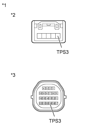 |
Disconnect the ATF temperature sensor assembly connector.
Remove the TCM.
Measure the resistance according to the value(s) in the table below.
| Tester Connection | Condition | Specified Condition |
| TPS3 ATF temperature sensor assembly side - 19 (TPS3) TCM side | Always | Below 1 Ω |
| TPS3 ATF temperature sensor assembly side - Body ground (valve body assembly) or any other terminals except 19 (TPS3) TCM side | Always | 10 kΩ or higher |
| *1 | Transmission Wire |
| *2 | ATF Temperature Sensor Assembly Side |
| *3 | TCM Side |
|
| ||||
| OK | |
|
| 3.REPLACE NO. 3 ATF PRESSURE SWITCH (ATF TEMPERATURE SENSOR ASSEMBLY) |
Replace the ATF temperature sensor assembly (Click here).
| NEXT | |
|
| 4.CHECK IF DTC OUTPUT RECURS (DTC P0989) |
Connect the intelligent tester to the DLC3.
Turn the ignition switch to ON.
Turn the intelligent tester on.
Enter the following menus: Powertrain / ECT / DTC / Clear.
Perform the monitor drive pattern (Click here).
Enter the following menus: Powertrain / ECT / DTC.
Read the DTCs using the intelligent tester.
| Result | Proceed to |
| Only P0989 is output | A |
| DTCs are not output | B |
|
| ||||
| A | ||
 | ||
| ||
| 5.INSPECT TRANSMISSION WIRE (NO. 3 ATF PRESSURE SWITCH) |
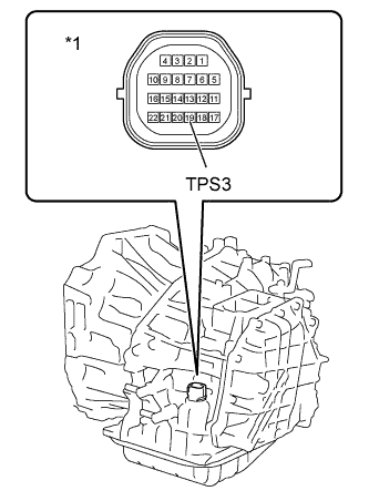 |
Remove the TCM.
Measure the resistance according to the value(s) in the table below.
| Tester Connection | Condition | Specified Condition |
| 19 (TPS3) - Body ground | Always | 10 kΩ or higher |
| *1 | Component without TCM connected (Transmission Wire) |
|
| ||||
| OK | ||
| ||
| ||
| 6.INSPECT NO. 3 ATF PRESSURE SWITCH |
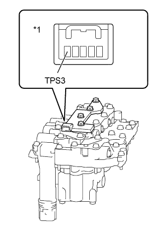 |
Disconnect the ATF temperature sensor assembly connector.
Measure the resistance according to the value(s) in the table below.
| Tester Connection | Condition | Specified Condition |
| TPS3 - Body ground (valve body assembly) or other terminals | Always | 10 kΩ or higher |
| *1 | Component without harness connected (ATF Temperature Sensor Assembly) |
|
| ||||
| OK | ||
| ||
| ||