| B |  |
| GO TO DTC CHART (Click here) |
DTC P0014 Camshaft Position "B" - Timing Over-Advanced or System Performance (Bank 1) |
DTC P0015 Camshaft Position "B" - Timing Over-Retarded (Bank 1) |
| DTC No. | DTC Detection Condition | Trouble Area |
| P0014 | The valve timing is not adjusted in the exhaust valve timing advance range (2 trip detection logic). |
|
| P0015 | The valve timing is not adjusted in the exhaust valve timing retard range (1 trip detection logic). |
|
| 1.CHECK ANY OTHER DTCS OUTPUT (IN ADDITION TO DTC P0014 OR P0015) |
Connect the intelligent tester to the DLC3.
Turn the ignition switch to ON.
Turn the tester on.
Enter the following menus: Powertrain / Engine and ECT / DTC.
Read the DTCs.
| Result | Proceed to |
| DTC P0014 or P0015 is output | A |
| DTC P0014 or P0015 and other DTCs are output | B |
|
| ||||
| A | |
 |
| 2.INSPECT CAMSHAFT TIMING OIL CONTROL VALVE ASSEMBLY |
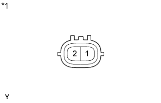 |
Remove the camshaft timing oil control valve assembly.
Measure the resistance according to the value(s) in the table below.
| Tester Connection | Condition | Specified Condition |
| 1 - 2 | 20°C (68°F) | 6.9 to 7.9 Ω |
| *1 | Component without harness connected (Camshaft Timing Oil Control Valve) |
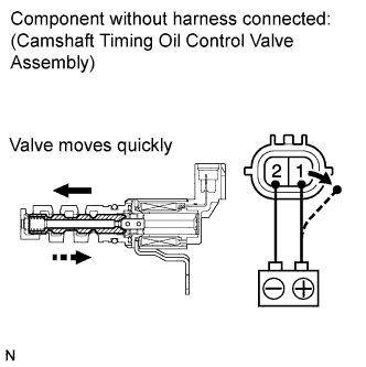 |
Apply positive (+) battery voltage to terminal 1 and negative (-) battery voltage to terminal 2. Check the valve operation.
Reinstall the camshaft timing oil control valve assembly.
|
| ||||
| OK | |
|
| 3.INSPECT CAMSHAFT TIMING GEAR ASSEMBLY |
Inspect the camshaft timing gear assembly .
|
| ||||
| OK | |
|
| 4.ADJUST VALVE TIMING |
| NEXT | |
|
| 5.CHECK WHETHER DTC OUTPUT RECURS (DTC P0014 OR P0015) |
Connect the intelligent tester to the DLC3.
Turn the ignition switch to ON.
Turn the tester on.
Clear the DTCs (Click here).
Start the engine and warm it up.
Switch the ECM from normal mode to check mode using the tester.
Drive the vehicle for more than 10 minutes.
Enter the following menus: Powertrain / Engine and ECT / DTC.
Read the DTCs.
| Result | Proceed to |
| DTC is not output | A |
| DTC P0014 or P0015 is output | B |
|
| ||||
| A | ||
 | ||
| ||