Home › Vehicle Interior › HEATING / AIR CONDITIONING › AIR CONDITIONING SYSTEM(for Manual Air Conditioning System)
RM30B0U _58 Vehicle Interior _009988 HEATING / AIR CONDITIONING _0054779 AIR CONDITIONING SYSTEM(for Manual Air Conditioning System) J

HEATING / AIR CONDITIONING  AIR CONDITIONING SYSTEM(for Manual Air Conditioning System)  Air Conditioning Compressor Magnetic Clutch Circuit  


DESCRIPTION

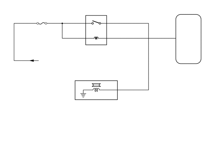
When the air conditioning amplifier assembly is turned on, a magnet clutch assembly signal is sent from the MGC terminal of the air conditioning amplifier assembly. Then, the MG/CLT relay turns on to operate the magnet clutch assembly.

WIRING DIAGRAM
E271242
5.813,2.188 6.271,2.385 0.458,0.198 10 false G80 5.813,2.375 7.031,2.792 1.219,0.417 10 false Air Conditioning Amplifier Assembly 5.99,1.229 6.448,1.427 0.458,0.198 10 false MGC 5.729,1.115 5.938,1.302 0.208,0.188 10 false 16 3.646,1.115 3.854,1.302 0.208,0.188 10 false 2 2.75,1.115 2.958,1.302 0.208,0.188 10 false 1 3.646,0.594 3.854,0.781 0.208,0.188 10 false 3 2.76,0.594 2.969,0.781 0.208,0.188 10 false 5 1.208,0.865 1.708,1.052 0.5,0.188 10 false HTR-IG 2.802,1.563 3.917,1.771 1.115,0.208 10 false MG/CLT Relay 1.354,1.979 2.771,2.219 1.417,0.24 10 false from IG1 NO.1 Relay 4.01,2.875 4.469,3.073 0.458,0.198 10 false 3 3.625,3.073 4.083,3.271 0.458,0.198 10 false MG+ 2.51,3.427 2.969,3.625 0.458,0.198 10 false B68 2.51,3.573 4.146,3.802 1.635,0.229 10 false Magnet Clutch Assembly

CAUTION / NOTICE / HINT

NOTICE:

Inspect the fuses for circuits related to this system before performing the following inspection procedure.


PROCEDURE
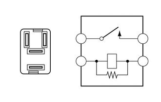
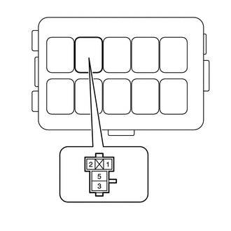
1.INSPECT MAGNET CLUTCH RELAY (MG/CLT)
a.
E271258
0.281,0.698 0.406,0.698 0.406,0.698 0.563,0.833 true 0.438,1.75 0.563,1.75 0.563,1.75 0.74,1.448 true 1.156,0.667 1.063,0.667 1.063,0.667 0.958,0.865 true 1.208,1.25 1.115,1.25 1.115,1.25 0.792,1.104 true 1.698,1.229 1.854,1.427 0.156,0.198 10 false 2 0.146,0.635 0.302,0.833 0.156,0.198 10 false 1 3.021,1.229 3.177,1.427 0.156,0.198 10 false 1 3.021,0.74 3.177,0.938 0.156,0.198 10 false 5 1.698,0.74 1.854,0.938 0.156,0.198 10 false 3 1.219,0.604 1.375,0.802 0.156,0.198 10 false 2 0.292,1.688 0.448,1.885 0.156,0.198 10 false 3 1.25,1.167 1.406,1.365 0.156,0.198 10 false 5

Remove the MG/CLT relay from the No. 2 engine room relay block.


b.

Measure the resistance according to the value(s) in the table below.

Standard Resistance:
Tester Connection Condition Specified Condition
3 - 5 Battery voltage is not applied to terminals 1 and 2 10 kΩ or higher
Battery voltage is applied to terminals 1 and 2 Below 1 Ω


Result:
Proceed to
OK
NG


OK

2.INSPECT MAGNET CLUTCH ASSEMBLY

NG

REPLACE MAGNET CLUTCH RELAY (MG/CLT)

2.INSPECT MAGNET CLUTCH ASSEMBLY
a.
E198322
1.302,1.792 1.646,1.385 false 1.135,1.813 1.5,1.99 0.365,0.177 10 MG+

Remove the cooler compressor assembly.

Click hereVehicle Interior>HEATING / AIR CONDITIONING>COMPRESSOR>REMOVAL


b.

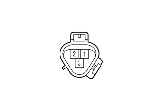
Apply battery voltage to the magnet clutch assembly and check the operation of the magnet clutch assembly.

OK:
Measurement Condition Specified Condition
Battery positive (+) → Terminal 3 (MG+)
Battery negative (-) → Body ground
Magnet clutch assembly operating sound can be heard, and magnet clutch hub and rotor lock.


Result:
Proceed to
OK
NG


OK

3.CHECK HARNESS AND CONNECTOR (NO. 2 ENGINE ROOM RELAY BLOCK - BATTERY)

NG

3.CHECK HARNESS AND CONNECTOR (NO. 2 ENGINE ROOM RELAY BLOCK - BATTERY)
a.
E271243
0.042,0.042 0.354,0.24 0.313,0.198 10 *a 1.25,0.625 1.563,0.823 0.313,0.198 10 *1
*1 MG/CLT Relay
*a Component without relay installed
(No. 2 Engine Room Relay Block)


Remove the MG/CLT relay from the No. 2 engine room relay block.


b.

Measure the voltage according to the value(s) in the table below.

Standard Voltage:
Tester Connection Condition Specified Condition
MG/CLT relay terminal 1 - Body ground Ignition switch ON 11 to 14 V
MG/CLT relay terminal 1 - Body ground Ignition switch off Below 1 V
MG/CLT relay terminal 5 - Body ground Always 11 to 14 V


Result:
Proceed to
OK
NG


OK

4.CHECK HARNESS AND CONNECTOR (AIR CONDITIONING AMPLIFIER ASSEMBLY - BATTERY)

NG

REPAIR OR REPLACE HARNESS OR CONNECTOR

4.CHECK HARNESS AND CONNECTOR (AIR CONDITIONING AMPLIFIER ASSEMBLY - BATTERY)
a.
E269937
1.49,0.229 1.927,0.438 0.438,0.208 2.229,1.75 2.083,1.75 2.083,1.75 1.875,1.24 true 2.292,1.688 2.75,1.885 0.458,0.198 10 MGC 0.094,0.073 0.552,0.271 0.458,0.198 10 *a 1.563,0.26 2.021,0.458 0.458,0.198 10 G80
*a Rear view of wire harness connector
(to Air Conditioning Amplifier Assembly)


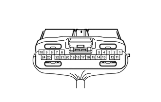
Disconnect the air conditioning amplifier assembly connector.


b.

Measure the voltage according to the value(s) in the table below.

Standard Voltage:
Tester Connection Switch Condition Specified Condition
G80-16 (MGC) - Body ground Ignition switch off Below 1 V
G80-16 (MGC) - Body ground Ignition switch ON 11 to 14 V


Result:
Proceed to
OK
NG


OK

5.CHECK HARNESS AND CONNECTOR (NO. 2 ENGINE ROOM RELAY BLOCK - COOLER COMPRESSOR ASSEMBLY)

NG

REPAIR OR REPLACE HARNESS OR CONNECTOR

5.CHECK HARNESS AND CONNECTOR (NO. 2 ENGINE ROOM RELAY BLOCK - COOLER COMPRESSOR ASSEMBLY)
a.

Remove the MG/CLT relay from the No. 2 engine room relay block.


b.

Disconnect the B68 cooler compressor assembly connector.


c.

Measure the resistance according to the value(s) in the table below.

Standard Resistance:
Tester Connection Condition Specified Condition
MG/CLT relay terminal 3 - B68-3 (MG+) Always Below 1 Ω
B68-3 (MG+) - Body ground Always 10 kΩ or higher


Result:
Proceed to
OK
NG


OK

NG

REPAIR OR REPLACE HARNESS OR CONNECTOR