STEERING COLUMN STEERING COLUMN ASSEMBLY INSTALLATION
PROCEDURE

 1.INSTALL NO. 2 STEERING INTERMEDIATE SHAFT ASSEMBLY
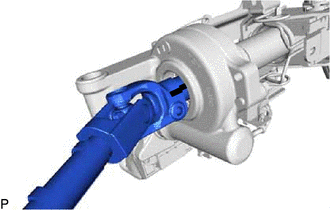
| *a | Matchmark |
Align the matchmarks on the No. 2 steering intermediate shaft assembly and steering column assembly.
Install the bolt.
- Torque:
- 35.3 N*m (360 kgf*cm, 26 ft.*lbf)
2.INSTALL ELECTRIC POWER STEERING COLUMN SUB-ASSEMBLY
Install the steering column assembly with the bolt and 2 nuts.
- Torque:
- for Nut : 25 N*m (255 kgf*cm, 18 ft.*lbf)
- for Bolt : 36 N*m (367 kgf*cm, 27 ft.*lbf)
- NOTICE:
- ·
Do not damage the 2 bushings.
·Do not line-up the bolt hole by prying on the collar or bushings. Only install the bolt straight, without applying any force to the bushings.
Connect the connectors and attach the wire harness clamps to the steering column assembly.
Connect the wire harness with the bolt.
- Torque:
- 8.35 N*m (85 kgf*cm, 74 in.*lbf)
3.PLACE FRONT WHEELS FACING STRAIGHT AHEAD
4.CONNECT NO. 2 STEERING INTERMEDIATE SHAFT ASSEMBLY
Align the matchmarks on the No. 2 steering intermediate shaft assembly and steering intermediate shaft assembly.
Install the bolt.
- Torque:
- 35.3 N*m (360 kgf*cm, 26 ft.*lbf)
5.INSTALL UPPER INSTRUMENT PANEL
6.INSTALL COLUMN HOLE COVER SILENCER SHEET
Install the column hole cover silencer sheet with the 2 clips.
Install the floor carpet.
7.INSTALL NO. 1 LOWER INSTRUMENT PANEL AIRBAG ASSEMBLY
8.INSTALL NO. 1 INSTRUMENT PANEL UNDER COVER SUB-ASSEMBLY
9.INSTALL COMBINATION SWITCH ASSEMBLY WITH SPIRAL CABLE SUB-ASSEMBLY
Attach the 2 claws to install the combination switch assembly with spiral cable sub-assembly to the steering column assembly.
Connect the connectors to the combination switch assembly with spiral cable sub-assembly.
10.INSTALL STEERING COLUMN COVER
Attach the 4 clips, 3 claws and 2 pins to install the upper steering column cover.
Attach the 2 claws to install the lower steering column cover.
Attach the 3 claws.
11.INSTALL STEERING WHEEL ASSEMBLY
12.INSPECT STEERING WHEEL CENTER POINT
13.CONNECT CABLE TO NEGATIVE BATTERY TERMINAL
- NOTICE:
-
When disconnecting the cable, some systems need to be initialized after the cable is reconnected (Click hereGeneral>INTRODUCTION>REPAIR INSTRUCTION>INITIALIZATION).
14. INITIALIZE ROTATION ANGLE SENSOR AND CALIBRATE TORQUE SENSOR ZERO POINT
15.CHECK SRS WARNING LIGHT