2AD-FTV LUBRICATION ENGINE OIL COOLER INSTALLATION
CAUTION / NOTICE / HINT
- NOTICE:
- ·
When replacing the injectors (including shuffling the injectors between the cylinders), common rail, intake manifold or cylinder head, it is necessary to replace the injection pipes with new ones.
·When replacing the fuel supply pump, common rail, intake manifold or cylinder head, it is necessary to replace the fuel inlet pipe with a new one.
PROCEDURE

 15710
1.INSTALL OIL COOLER ASSEMBLY
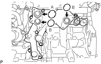
Apply engine oil to the 2 new O-rings labeled B in the illustration.
- NOTICE:
-
Do not apply engine oil to the new O-ring labeled A in the illustration.
Install the 3 new O-rings to the No. 1 oil cooler bracket.
Install the oil cooler assembly with the 5 bolts.
- Torque:
- 10 N*m (102 kgf*cm, 7 ft.*lbf)
16261
2.INSTALL WATER BY-PASS HOSE
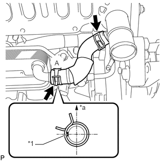
| *1 | Paint Mark |
| *a | Upper Side |
Install the water by-pass hose to the water outlet and oil cooler assembly, and slide the 2 clamps to secure the hose.
- HINT:
-
Make sure the claws of hose clamp A are positioned above the paint mark as shown in the illustration.
17111
3.INSTALL INTAKE MANIFOLD
25770A
4.CONNECT NO. 2 VACUUM TRANSMITTING HOSE ASSEMBLY
17112
5.INSTALL NO. 2 INTAKE MANIFOLD
12631A
6.INSTALL ENGINE COVER BRACKET
17696
7.INSTALL GAS FILTER BRACKET
23265
8.INSTALL NO. 1 GAS FILTER
89421C
9.INSTALL DIESEL TURBO PRESSURE SENSOR
11452
10.INSTALL ENGINE OIL LEVEL DIPSTICK GUIDE
17853B
11.INSTALL INTAKE MANIFOLD INSULATOR
23810A
12.INSTALL COMMON RAIL ASSEMBLY
23701
13.INSTALL INJECTION PIPE SUB-ASSEMBLY
23804C
14.INSTALL FUEL INLET PIPE SUB-ASSEMBLY
25800
15.INSTALL ELECTRIC EGR CONTROL VALVE ASSEMBLY
25602
16.INSTALL NO. 2 EGR PIPE SUB-ASSEMBLY
16296
17.CONNECT NO. 8 WATER BY-PASS HOSE
16295
18.INSTALL NO. 7 WATER BY-PASS HOSE
25625
19.INSTALL EGR VALVE BRACKET
20.CONNECT ENGINE WIRE
26100
21.INSTALL DIESEL THROTTLE BODY ASSEMBLY
22.ADD ENGINE OIL
23.CONNECT CABLE TO NEGATIVE BATTERY TERMINAL
- NOTICE:
-
When disconnecting the cable, some systems need to be initialized after the cable is reconnected.
-
Click hereGeneral>INTRODUCTION>REPAIR INSTRUCTION>INITIALIZATION
24.ADD ENGINE COOLANT
25.BLEED AIR FROM FUEL SYSTEM
26.INSPECT FOR COOLANT LEAK
27.INSPECT FOR OIL LEAK
28.INSPECT FOR FUEL LEAK
29.INSPECT ENGINE OIL LEVEL