GF1A TRANSFER / 4WD / AWD DYNAMIC TORQUE CONTROL 4WD/AWD SYSTEM C1297/97 Steering Angle Sensor
DESCRIPTION
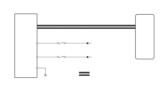
The 4WD ECU assembly determines that the vehicle is turning based on the signals sent from the steering angle sensor (spiral with sensor cable sub-assembly).
The steering angle sensor signal is sent to the 4WD ECU assembly via the CAN communication system.
| DTC No. | Detection Item | DTC Detection Condition | Trouble Area |
|---|---|---|---|
| C1297/97 | Steering Angle Sensor | When voltage of 4WD ECU assembly IG terminal is 9.5 V or more, and steering angle sensor (spiral with sensor cable sub-assembly) malfunction signal is received. | ·
ECU-B NO. 1 fuse ·
Steering angle sensor (Spiral with sensor cable sub-assembly) ·
CAN communication system ·
4WD ECU assembly ·
Wire harness and connector |
WIRING DIAGRAM
CAUTION / NOTICE / HINT
- NOTICE:
-
Inspect the fuses for circuits related to this system before performing the following inspection procedure.
- HINT:
-
Check the condition of each related circuit connector before troubleshooting.
PROCEDURE
Clear the DTC.
Click hereDrivetrain>GF1A TRANSFER / 4WD / AWD>DYNAMIC TORQUE CONTROL 4WD/AWD SYSTEM>DTC CHECK / CLEAR
- Chassis > Four Wheel Drive > Clear DTCs
- 50002 118
Turn the ignition switch off.
Turn the ignition switch to ON again and check that no CAN communication system DTC(s) is output.
for LHD: Click herePower Source / Network>NETWORKING>CAN COMMUNICATION SYSTEM(for LHD)>DIAGNOSIS SYSTEM
for RHD: Click herePower Source / Network>NETWORKING>CAN COMMUNICATION SYSTEM(for RHD)>DIAGNOSIS SYSTEM
Start the engine.
Drive the vehicle at a speed of 35 km/h (24 mph), turn the steering wheel to the right and left and check that no brake control system (steering angle sensor) DTC (C1432, C1433 or C1434) is output.
Click hereBrake>BRAKE CONTROL / DYNAMIC CONTROL SYSTEMS>VEHICLE STABILITY CONTROL SYSTEM>DTC CHECK / CLEAR
- Chassis > ABS/VSC/TRC > Trouble Codes
- 50001 105
- Result:
Result Proceed to Neither CAN communication system DTC nor brake control system DTC is output A CAN communication system DTC is output (for LHD) B CAN communication system DTC is output (for RHD) C Brake control system (steering angle sensor) DTC (C1432, C1433 or C1434) is output D
- HINT:
-
When DTCs indicating a CAN communication system malfunction are output, repair the CAN communication system before repairing each corresponding sensor.
A
B
C
D
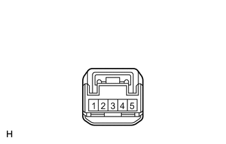
| *a | Front view of wire harness connector
(to Steering Angle Sensor [Spiral with Sensor Cable Sub-assembly]) |
Remove the steering wheel and the column cover lower.
Click hereSteering>STEERING COLUMN>STEERING COLUMN ASSEMBLY>REMOVAL
Make sure that there is no looseness at the locking part and the connecting part of the connectors.
Disconnect the steering angle sensor (spiral with sensor cable sub-assembly) connector.
Turn the ignition switch to ON.
Measure the voltage according to the value(s) in the table below.
- Standard Voltage:
Tester Connection Condition Specified Condition G12-4 (IG) - Body ground Ignition switch ON 11 to 14 V G12-5 (BAT) - Body ground Always 11 to 14 V
- Result:
Proceed to OK NG
OK
NG
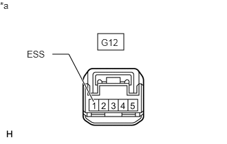
| *a | Front view of wire harness connector
(to Steering Angle Sensor [Spiral with Sensor Cable Sub-assembly]) |
Turn the ignition switch off.
Measure the resistance according to the value(s) in the table below.
- Standard Resistance:
Tester Connection Condition Specified Condition G12-1 (ESS) - Body ground Always Below 1 Ω
- Result:
Proceed to OK NG
OK
NG
Connect the GTS to the DLC3.
Turn the ignition switch to ON.
Turn the GTS on.
Enter the following menus: Chassis / Four Wheel Drive / Data List.
Read the value displayed on the GTS.
- Chassis > Four Wheel Drive > Data List
-
Tester Display Measurement Item Range Normal Condition Diagnostic Note Steering Angle Value Steering angle value Min.: -3276.8°
Max.: 3276.7°Left turn: Increase
Right turn: DecreaseChanges in proportion with the amount of steering wheel rotation during steering operation.
- Chassis > Four Wheel Drive > Data List
-
Tester Display Steering Angle Value - 50003 118 8
- OK:
The steering angle sensor value changes in accordance with the steering wheel movement.
- Result:
Proceed to OK NG
OK
NG