Home › Engine / Hybrid System › 2AD-FHV ENGINE CONTROL › ECD SYSTEM
RM3090E _51 Engine / Hybrid System _008730 2AD-FHV ENGINE CONTROL _0049704 ECD SYSTEM J

2AD-FHV ENGINE CONTROL  ECD SYSTEM  Starter Signal Circuit  


DESCRIPTION

While the engine is being cranked, current flows from terminal ST2 of the ignition or starter switch assembly*1 or terminal STAR of the certification ECU (smart key ECU assembly)*2 to the clutch start switch assembly and to terminal STA of the ECM (STA signal).

*1: w/o entry and start system

*2: w/ entry and start system


WIRING DIAGRAM
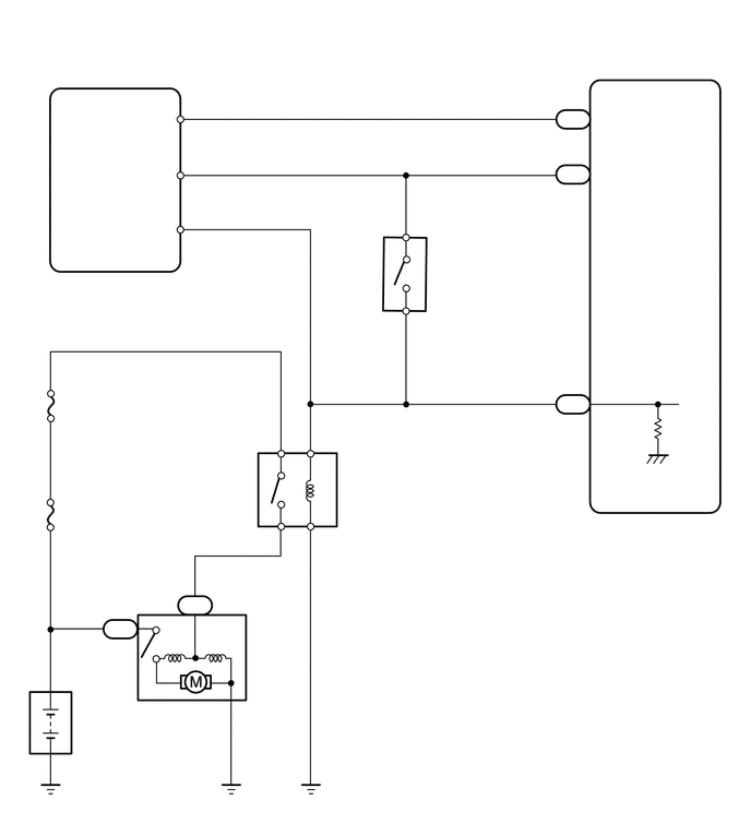
A284209
0.104,0.094 4.521,0.573 4.417,0.479 12 false w/ Entry and Start System: 0.198,2.625 2.51,3.177 2.313,0.552 10 false Certification ECU (Smart Key ECU Assembly) 0.188,2.438 0.646,2.635 0.458,0.198 10 false G82 1.271,1.594 1.938,1.875 0.667,0.281 10 false STAR 1.438,1.063 1.802,1.323 0.365,0.26 10 false NE 1.375,2.104 2.042,2.385 0.667,0.281 10 false STA 1.75,0.948 2.073,1.198 0.323,0.25 10 false 16 1.781,1.5 2.104,1.75 0.323,0.25 10 false 5 1.792,2 2.115,2.25 0.323,0.25 10 false 7 5.344,1.052 5.667,1.302 0.323,0.25 10 false A61 5.375,1.406 5.698,1.656 0.323,0.25 10 false 38 5.354,3.781 5.677,4.031 0.323,0.25 10 false A61 5.344,1.583 5.667,1.833 0.323,0.25 10 false B76 5.375,3.573 5.698,3.823 0.323,0.25 10 false 43 5.688,3.667 6.354,3.948 0.667,0.281 10 false STA 5.688,1.583 6.354,1.865 0.667,0.281 10 false NSW 5.688,1.052 6.354,1.333 0.667,0.281 10 false NEO 6.104,5.01 6.771,5.292 0.667,0.281 10 false ECM 3.271,4.542 3.719,4.833 0.448,0.292 10 false ST 0.563,3.781 1.01,4.073 0.448,0.292 10 false ST 0.563,4.865 1.458,5.198 0.896,0.333 10 false FL MAIN 1.51,6.74 2.406,7.073 0.896,0.333 10 false Starter 0.719,6.771 1.615,7.104 0.896,0.333 10 false Battery 1.031,5.917 1.375,6.177 0.344,0.26 10 false C4 1.76,5.698 2.104,5.958 0.344,0.26 10 false B6 1.125,5.719 1.448,5.969 0.323,0.25 10 false 1 1.604,5.698 1.927,5.948 0.323,0.25 10 false 1 3.083,5.073 3.406,5.323 0.323,0.25 10 false 1 3.052,4.104 3.375,4.354 0.323,0.25 10 false 2 2.521,4.104 2.844,4.354 0.323,0.25 10 false 5 2.5,5.063 2.823,5.313 0.323,0.25 10 false 3 4.177,2.24 4.5,2.49 0.323,0.25 10 false B36 4.135,2.448 5.208,3.615 1.073,1.167 10 false Park/Neutral Position Switch Assembly 3.698,2.052 4.021,2.302 0.323,0.25 10 false 4 3.698,2.99 4.021,3.24 0.323,0.25 10 false 9 5.375,0.885 5.698,1.135 0.323,0.25 10 false 10 3.698,2.302 4.021,2.552 0.323,0.25 10 false B 3.719,2.771 4.042,3.021 0.323,0.25 10 false L

A284210
4.219,2.24 5.417,3.021 1.198,0.781 10 false Park/Neutral Position Switch Assembly 0.073,0.115 4.573,0.792 4.5,0.677 12 false w/o Entry and Start System: 1.51,1.813 2.875,2.146 1.365,0.333 10 false Ignition Switch 2.146,1.156 2.458,1.354 0.313,0.198 10 false ST2 4.198,2.021 4.51,2.219 0.313,0.198 10 false B36 1.521,1.146 1.833,1.344 0.313,0.198 10 false AM2 1.229,1.604 1.542,1.802 0.313,0.198 10 false G4 1.313,1.177 1.625,1.375 0.313,0.198 10 false 4 2.552,1.188 2.865,1.385 0.313,0.198 10 false 2 5.344,1.281 5.656,1.479 0.313,0.198 10 false B76 5.344,3.563 5.656,3.76 0.313,0.198 10 false A61 5.396,1.063 5.708,1.26 0.313,0.198 10 false 38 5.406,3.375 5.719,3.573 0.313,0.198 10 false 43 5.719,1.281 6.26,1.521 0.542,0.24 10 false NSW 5.698,3.438 6.24,3.677 0.542,0.24 10 false STA 3.271,4.313 3.813,4.552 0.542,0.24 10 false ST 1.521,3.219 2.063,3.458 0.542,0.24 10 false ST 0.594,2.188 1.135,2.427 0.542,0.24 10 false AM2 0.563,4.719 1.927,5.052 1.365,0.333 10 false FL MAIN 1.563,6.49 2.927,6.823 1.365,0.333 10 false Starter 0.75,6.573 2.115,6.906 1.365,0.333 10 false Battery 6.115,4.875 6.656,5.115 0.542,0.24 10 false ECM 1.052,5.698 1.594,5.938 0.542,0.24 10 false C4 1.771,5.479 2.313,5.719 0.542,0.24 10 false B6 1.094,5.521 1.635,5.76 0.542,0.24 10 false 1 1.573,5.469 2.115,5.708 0.542,0.24 10 false 1 3.094,4.823 3.635,5.063 0.542,0.24 10 false 1 3.094,3.896 3.635,4.135 0.542,0.24 10 false 2 2.531,3.896 3.073,4.135 0.542,0.24 10 false 5 2.51,4.813 3.052,5.052 0.542,0.24 10 false 3 3.76,1.833 4.073,2.031 0.313,0.198 10 false 4 3.74,2.771 4.052,2.969 0.313,0.198 10 false 9 3.76,2.094 4.073,2.292 0.313,0.198 10 false B 3.76,2.531 4.073,2.729 0.313,0.198 10 false L

CAUTION / NOTICE / HINT

NOTICE:
·

Inspect the fuses of circuits related to this system before performing the following inspection procedure.

·

After replacing the ECM, the new ECM needs registration (Click here Engine / Hybrid System>2AD-FHV ENGINE CONTROL>ECD SYSTEM>REGISTRATION) and initialization (Click here Engine / Hybrid System>2AD-FHV ENGINE CONTROL>ECD SYSTEM>INITIALIZATION).


PROCEDURE

1.CHECK WHETHER ENGINE CAN BE CRANKED
a.

Check if the engine can be cranked.

Result:
Proceed to
Engine cannot be cranked
Engine can be cranked


Engine cannot be cranked

2.READ VALUE USING GTS (STARTER SIGNAL)

Engine can be cranked

16.READ VALUE USING GTS (STARTER SIGNAL)
2.READ VALUE USING GTS (STARTER SIGNAL)
a.

Connect the GTS to the DLC3.


b.

Turn the ignition switch to ON.


c.

Turn the GTS on.


d.

Enter the following menus: Powertrain / Engine / Data List / All Data / Starter Signal.

Powertrain > Engine > Data List
Tester Display
Starter Signal
50003 61 193

e.

Check the value displayed on the GTS when the ignition switch is turned to the ON and START positions.

OK:
Switch Position Starter Signal
ON OFF
START ON


Result:
Proceed to
OK
NG


OK

3.INSPECT ST RELAY

NG

10.INSPECT PARK/NEUTRAL POSITION SWITCH ASSEMBLY
3.INSPECT ST RELAY

Result:
Proceed to
OK
NG


OK

4.INSPECT STARTER ASSEMBLY

NG

REPLACE ST RELAY

4.INSPECT STARTER ASSEMBLY
a.

Inspect the starter assembly.

Click hereEngine / Hybrid System>2AD-FHV STARTING>STARTER>INSPECTION


Result:
Proceed to
OK
NG


OK

5.CHECK HARNESS AND CONNECTOR (ST RELAY - STARTER ASSEMBLY)

NG

REPLACE STARTER ASSEMBLY

5.CHECK HARNESS AND CONNECTOR (ST RELAY - STARTER ASSEMBLY)
a.

Remove the ST relay from the engine room relay block and junction block assembly.


b.

Disconnect the starter assembly connector.


c.

Measure the resistance according to the value(s) in the table below.

Standard Resistance:
Tester Connection Condition Specified Condition
3 (ST relay) - B6-1 Always Below 1 Ω
3 (ST relay) or B6-1 - Body ground Always 10 kΩ or higher


Result:
Proceed to
OK
NG


OK

6.CHECK TERMINAL VOLTAGE (POWER SOURCE OF STARTER ASSEMBLY)

NG

REPAIR OR REPLACE HARNESS OR CONNECTOR

6.CHECK TERMINAL VOLTAGE (POWER SOURCE OF STARTER ASSEMBLY)
a.

Disconnect the starter assembly connector.


b.

Measure the voltage according to the value(s) in the table below.

Standard Voltage:
Tester Connection Condition Specified Condition
C4-1 - Body ground Always 11 to 14 V


Result:
Proceed to
OK
NG


OK

7.CHECK TERMINAL VOLTAGE (POWER SOURCE OF ST RELAY)

NG

REPAIR OR REPLACE HARNESS OR CONNECTOR

7.CHECK TERMINAL VOLTAGE (POWER SOURCE OF ST RELAY)
a.
A296486
0.094,0.146 0.406,0.302 0.313,0.156 10 *1 2.073,3.51 2.385,3.667 0.313,0.156 10 *2
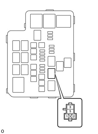
*1 Engine Room NO. 2 Relay Block and Junction Block Assembly
*2 ST Relay


Remove the ST relay from the engine room NO. 2 relay block and junction block assembly.


b.

Measure the voltage according to the value(s) in the table below.

Standard Voltage:
Tester Connection Condition Specified Condition
5 (ST relay) - Body ground Always 11 to 14 V


Result:
Proceed to
OK
NG


OK

8.CHECK HARNESS AND CONNECTOR (ST RELAY - BODY GROUND)

NG

REPAIR OR REPLACE HARNESS OR CONNECTOR (BATTERY - ST RELAY)

8.CHECK HARNESS AND CONNECTOR (ST RELAY - BODY GROUND)
a.

Remove the ST relay from the engine room NO. 2 relay block and junction block assembly.


b.

Measure the resistance according to the value(s) in the table below.

Standard Resistance:
Tester Connection Condition Specified Condition
1 (ST relay) - Body ground Always Below 1 Ω


Result:
Proceed to
OK
NG


OK

9.CHECK HARNESS AND CONNECTOR (ST RELAY - PARK/NEUTRAL POSITION SWITCH ASSEMBLY)

NG

REPAIR OR REPLACE HARNESS OR CONNECTOR

9.CHECK HARNESS AND CONNECTOR (ST RELAY - PARK/NEUTRAL POSITION SWITCH ASSEMBLY)
a.

Remove the ST relay from the engine room NO. 2 relay block and junction block assembly.


b.

Disconnect the park/neutral position switch assembly connector.


c.

Measure the resistance according to the value(s) in the table below.

Standard Resistance:
Tester Connection Condition Specified Condition
2 (ST relay) - B36-9 (L) Always Below 1 Ω
2 (ST relay) or B36-9 (L) - Body ground Always 10 kΩ or higher


Result:
Proceed to
OK
NG


OK

PROCEED TO NEXT SUSPECTED AREA SHOWN IN PROBLEM SYMPTOMS TABLE

NG

REPAIR OR REPLACE HARNESS OR CONNECTOR

10.INSPECT PARK/NEUTRAL POSITION SWITCH ASSEMBLY
a.

Inspect the park/neutral position switch assembly.

Click hereDrivetrain>U660F AUTOMATIC TRANSMISSION / TRANSAXLE>PARK / NEUTRAL POSITION SWITCH>INSPECTION


Result:
Proceed to
OK (w/ entry and start system)
OK (w/o entry and start system)
NG


OK (w/ entry and start system)

11.CHECK HARNESS AND CONNECTOR (CERTIFICATION ECU (SMART KEY ECU ASSEMBLY) - PARK/NEUTRAL POSITION SWITCH ASSEMBLY)

OK (w/o entry and start system)

13.INSPECT IGNITION OR STARTER SWITCH ASSEMBLY

NG

11.CHECK HARNESS AND CONNECTOR (CERTIFICATION ECU (SMART KEY ECU ASSEMBLY) - PARK/NEUTRAL POSITION SWITCH ASSEMBLY)
a.

Disconnect the certification ECU (smart key ECU assembly) connector.


b.

Disconnect the park/neutral position switch assembly connector.


c.

Measure the resistance according to the value(s) in the table below.

Standard Resistance:
Tester Connection Condition Specified Condition
G82-5 (STAR) - B36-4 (B) Always Below 1 Ω
G82-5 (STAR) or B36-4 (B) - Body ground Always 10 kΩ or higher


Result:
Proceed to
OK
NG


OK

12.CHECK HARNESS AND CONNECTOR (PARK/NEUTRAL POSITION SWITCH ASSEMBLY - ECM)

NG

REPAIR OR REPLACE HARNESS OR CONNECTOR

12.CHECK HARNESS AND CONNECTOR (PARK/NEUTRAL POSITION SWITCH ASSEMBLY - ECM)
a.

Disconnect the park/neutral position switch assembly connector.


b.

Remove the ST relay from the engine room relay block and junction block assembly.


c.

Disconnect the ECM connector.


d.

Disconnect the certification ECU (smart key ECU assembly) connector.


e.

Measure the resistance according to the value(s) in the table below.

Standard Resistance:
Tester Connection Condition Specified Condition
B36-9 (L) - A61-43 (STA) Always Below 1 Ω
B36-9 (L) or A61-43 (STA) - Body ground Always 10 kΩ or higher


Result:
Proceed to
OK
NG


OK

GO TO ENTRY AND START SYSTEM

NG

REPAIR OR REPLACE HARNESS OR CONNECTOR

13.INSPECT IGNITION OR STARTER SWITCH ASSEMBLY
a.

Inspect the ignition or starter switch assembly.

Click hereEngine / Hybrid System>2AD-FHV STARTING>IGNITION SWITCH>INSPECTION


Result:
Proceed to
OK
NG


OK

14.CHECK HARNESS AND CONNECTOR (IGNITION OR STARTER SWITCH ASSEMBLY - PARK/NEUTRAL POSITION SWITCH ASSEMBLY)

NG

REPLACE IGNITION OR STARTER SWITCH ASSEMBLY

14.CHECK HARNESS AND CONNECTOR (IGNITION OR STARTER SWITCH ASSEMBLY - PARK/NEUTRAL POSITION SWITCH ASSEMBLY)
a.

Disconnect the ignition or starter switch assembly connector.


b.

Disconnect the park/neutral position switch assembly connector.


c.

Measure the resistance according to the value(s) in the table below.

Standard Resistance:
Tester Connection Condition Specified Condition
G4-2 (ST2) - B36-4 (B) Always Below 1 Ω
G4-2 (ST2) or B36-4 (B) - Body ground Always 10 kΩ or higher


Result:
Proceed to
OK
NG


OK

15.CHECK HARNESS AND CONNECTOR (PARK/NEUTRAL POSITION SWITCH ASSEMBLY - ECM)

NG

REPAIR OR REPLACE HARNESS OR CONNECTOR

15.CHECK HARNESS AND CONNECTOR (PARK/NEUTRAL POSITION SWITCH ASSEMBLY - ECM)
a.

Disconnect the park/neutral position switch assembly connector.


b.

Remove the ST relay from the engine room NO. 2 relay block and junction block assembly.


c.

Disconnect the ECM connector.


d.

Measure the resistance according to the value(s) in the table below.

Standard Resistance:
Tester Connection Condition Specified Condition
B36-9 (L) - A61-43 (STA) Always Below 1 Ω
B36-9 (L) or A61-43 (STA) - Body ground Always 10 kΩ or higher


Result:
Proceed to
OK
NG


OK

REPAIR OR REPLACE HARNESS OR CONNECTOR (BATTERY - IGNITION OR STARTER SWITCH ASSEMBLY)

NG

REPAIR OR REPLACE HARNESS OR CONNECTOR

16.READ VALUE USING GTS (STARTER SIGNAL)
a.

Connect the GTS to the DLC3.


b.

Turn the ignition switch to ON.


c.

Turn the GTS on.


d.

Enter the following menus: Powertrain / Engine / Data List / All Data / Starter Signal.

Powertrain > Engine > Data List
Tester Display
Starter Signal
50003 61 193

e.

Check the value displayed on the GTS when the ignition switch is turned to the ON and START positions.

OK:
Switch Position Starter Signal
ON OFF
START ON


Result:
Proceed to
OK
NG


OK

PROCEED TO NEXT SUSPECTED AREA SHOWN IN PROBLEM SYMPTOMS TABLE

NG

REPAIR OR REPLACE HARNESS OR CONNECTOR (ST RELAY - ECM)