CLUTCH CLUTCH RELEASE CYLINDER(for Diesel) INSTALLATION
PROCEDURE

 31470
1.INSTALL CLUTCH RELEASE CYLINDER ASSEMBLY
Install the clutch release cylinder assembly and No. 1 clutch tube bracket with the 2 bolts.
- Torque:
- 12 N*m (122 kgf*cm, 9 ft.*lbf)
31482
2.CONNECT CLUTCH RELEASE CYLINDER TO FLEXIBLE HOSE TUBE
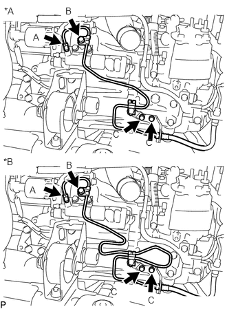
| *A | for LHD |
| *B | for RHD |
Temporarily install the clutch release cylinder to flexible hose tube labeled A.
Connect the clutch release cylinder to flexible hose tube with the 3 bolts.
- Torque:
- for bolt B : 8.0 N*m (82 kgf*cm, 71 in.*lbf)
- for bolt C : 19 N*m (194 kgf*cm, 14 ft.*lbf)
Using a union nut wrench, tighten the clutch release cylinder to flexible hose tube.
- Torque:
- 15 N*m (153 kgf*cm, 11 ft.*lbf)
- NOTICE:
-
Use the formula to calculate special torque values for situations where a union nut wrench is combined with a torque wrench. Click hereGeneral>INTRODUCTION>REPAIR INSTRUCTION>PRECAUTION
3.BLEED CLUTCH PIPE LINE
for 1AD-FTV:
Click hereDrivetrain>CLUTCH>CLUTCH SYSTEM(for 1AD-FTV)>BLEEDING
for 2AD-FTV:
Click hereDrivetrain>CLUTCH>CLUTCH SYSTEM(for 2AD-FTV)>BLEEDING
4.CHECK FOR BRAKE FLUID LEAKAGE
74414B
5.INSTALL BATTERY BRACKET REINFORCEMENT
for 1AD-FTV:
w/ Stop And Start System (Click hereEngine / Hybrid System>1AD-FTV STARTING>STARTER(w/ Stop And Start System)>INSTALLATION)
w/o Stop And Start System (Click hereEngine / Hybrid System>1AD-FTV STARTING>STARTER(w/o Stop And Start System)>INSTALLATION)
for 2AD-FTV:
Click hereEngine / Hybrid System>2AD-FTV STARTING>STARTER>INSTALLATION