HEATING / AIR CONDITIONING HEATER FUEL PUMP INSTALLATION
PROCEDURE

 87260
1.INSTALL HEATER PUMP ASSEMBLY
Connect the connector to the heater pump assembly.
for AD Series Engine:
Install the heater pump assembly and while pushing the bracket to the stud bolt, tighten the nut as shown in the illustration.
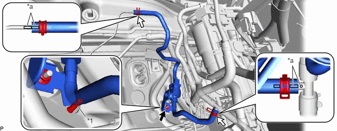
| *1 | Stud Bolt | - | - |
| *a | Marking | - | - |
- Torque:
- 9.8 N*m (100 kgf*cm, 87 in.*lbf)
Align the markings on each hose and pipe as shown in the illustration and connect them with the clips.
for 2WW:
Install the heater pump assembly and while pushing the bracket to the stud bolt, tighten the nut as shown in the illustration.
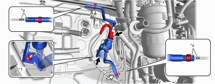
| *1 | Stud Bolt | - | - |
| *a | Marking | - | - |
- Torque:
- 9.8 N*m (100 kgf*cm, 87 in.*lbf)
Align the markings on each hose and pipe as shown in the illustration and connect them with the clips.
28610
2.INSTALL GLOW PLUG RELAY ASSEMBLY (for 2WW)
23921
3.INSTALL FUEL FILTER SUPPORT (for 2WW)
4.INSTALL FUEL FILTER ASSEMBLY (for 2WW)
5.INSTALL AIR CLEANER CASE SUB-ASSEMBLY (for 2WW)
17705
6.INSTALL AIR CLEANER CAP SUB-ASSEMBLY WITH AIR CLEANER HOSE ASSEMBLY (for 2WW)
55789D
7.INSTALL NO. 3 COWL TOP PANEL INSULATOR (for 2WW)
17705
8.INSTALL AIR CLEANER CAP SUB-ASSEMBLY
12611
9.INSTALL NO. 1 ENGINE COVER
for AD Series Engine:
Click hereEngine / Hybrid System>2AD-FHV ENGINE MECHANICAL>ENGINE ASSEMBLY>INSTALLATION
for 2WW:
Click hereEngine / Hybrid System>2WW ENGINE MECHANICAL>ENGINE ASSEMBLY>INSTALLATION