INTERIOR PANELS / TRIM LOWER INSTRUMENT PANEL INSTALLATION
CAUTION / NOTICE / HINT
- HINT:
- ·
Use the same procedure for RHD and LHD vehicles.
·The procedure listed below is for LHD vehicles.
·A bolt without a torque specification is shown in the standard bolt chart.
Click hereGeneral>SPECIFICATIONS>STANDARD BOLT>SPECIFIED TORQUE FOR STANDARD BOLTS
PROCEDURE

 1.INSTALL LOWER INSTRUMENT PANEL (for LHD)
Install the lower instrument panel with the bolt <G> and 2 bolts <C> or <D> and 6 bolts <E> or <F>.
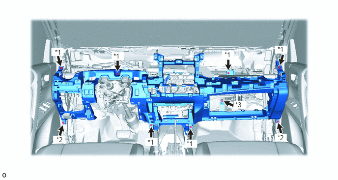
| *1 | Bolt <E> or <F> | *2 | Bolt <C> or <D> |
| *3 | Bolt <G> | - | - |
Attach the 2 claws to connect the cooler thermistor.
Attach the 2 claws to connect the DLC3.
Attach the claw to connect the hood lock control lever.
Connect each connector and attach each wire harness clamp.
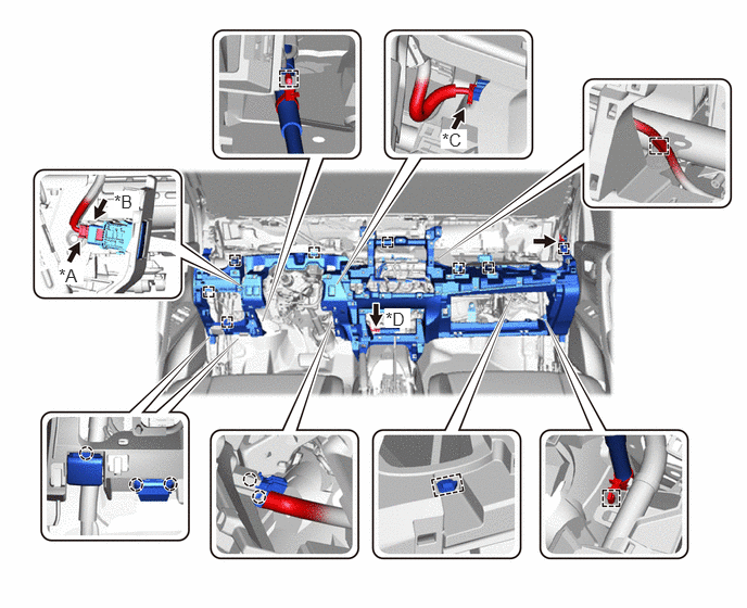
| *A | for 4WD/AWD | *B | w/ Power Back Door |
| *C | w/ Downhill Assist Control | *D | w/ Entry and Start System |
2.INSTALL LOWER INSTRUMENT PANEL (for RHD)
Install the lower instrument panel with the bolt <G> and 2 bolts <C> or <D> and 7 bolts <E> or <F>.
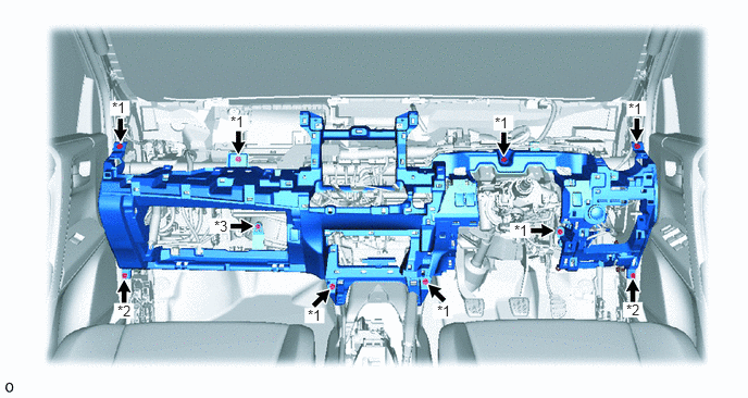
| *1 | Bolt <E> or <F> | *2 | Bolt <C> or <D> |
| *3 | Bolt <G> | - | - |
Attach the 2 claws to connect the cooler thermistor.
Attach the 2 claws to connect the DLC3.
Attach the claw to connect the hood lock control lever.
Connect each connector and attach each wire harness clamp.
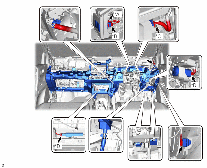
| *A | for 4WD/AWD | *B | w/ Power Back Door |
| *C | w/ Downhill Assist Control | *D | w/ Entry and Start System |
55870B
3.INSTALL HEATER TO REGISTER DUCT ASSEMBLY
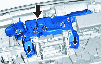
Lower the heater to register duct assembly to attach the 6 claws and install it.
Install the 2 clips.
55950G
4.INSTALL DEFROSTER NOZZLE ASSEMBLY
Attach the 3 claws to install the defroster nozzle assembly.
Attach the 2 wire harness clamps and connect the connector.
62112
5.INSTALL COWL SIDE TRIM BOARD LH
Attach the clip to install the cowl side trim board LH.
Install the nut.
62111C
6.INSTALL COWL SIDE TRIM BOARD RH
- HINT:
-
Use the same procedure described for the LH side.
67914B
7.INSTALL FRONT DOOR SCUFF PLATE LH
67913B
8.INSTALL FRONT DOOR SCUFF PLATE RH
55432B
9.INSTALL LOWER INSTRUMENT PANEL FINISH PANEL (for LHD without Driver Side Knee Airbag)
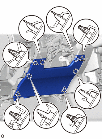
Attach the 4 clips and 4 claws to install the lower instrument panel finish panel.
73900
10.INSTALL LOWER NO. 1 INSTRUMENT PANEL AIRBAG ASSEMBLY (w/ Driver Side Knee Airbag)
55545
11.INSTALL FUSE BOX OPENING COVER
for LHD:
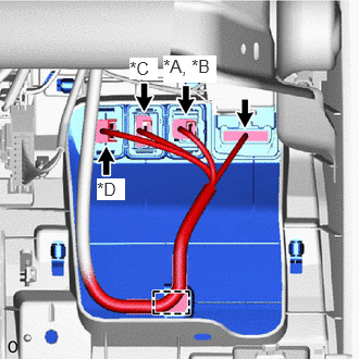
| *A | w/ Headlight Leveling |
| *B | w/ Light Control Rheostat |
| *C | w/ VSC OFF Switch |
| *D | w/ Blind Spot Monitor |
Connect each connector and attach the wire harness clamp.
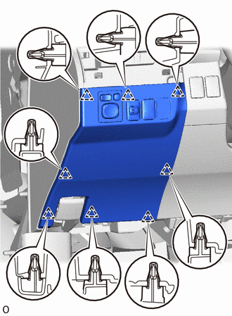
Attach the 8 clips to install the fuse box opening cover.
for RHD:
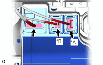
| *A | w/ VSC OFF Switch |
| *B | w/ Headlight Leveling |
Connect each connector.
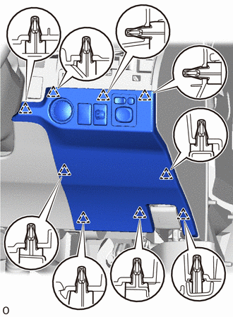
Attach the 9 clips to install the fuse box opening cover.
55607
12.INSTALL NO. 2 INSTRUMENT PANEL UNDER COVER SUB-ASSEMBLY
Attach the 2 guides and 2 claws to install the No. 2 instrument panel under cover sub-assembly.
w/ Foot Light:
Connect the connector.
55606
13.INSTALL NO. 1 INSTRUMENT PANEL UNDER COVER SUB-ASSEMBLY
w/ Tire Pressure Warning System:
Connect the connector.
w/ Foot Light:
Connect the connector.
Attach the 2 guides and 2 claws to install the No. 1 instrument panel under cover sub-assembly.
Install the 2 screws <A> or <B>.
55433B
14.INSTALL LOWER NO. 2 INSTRUMENT PANEL FINISH PANEL
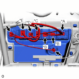
| *A | w/ Drive Mode Switch |
| *B | w/ Seat Heater System |
| *C | w/ PTC Heater |
| *D | for Windshield Deicer |
| *E | w/ USB Audio System |
for LHD:
Connect each connector.
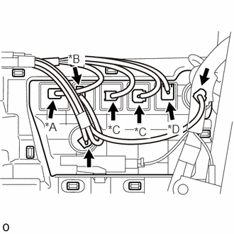
| *A | w/ Drive Mode Switch |
| *B | w/ Lane Departure Alert System |
| *C | w/ Seat Heater System |
| *D | w/ USB Audio System |
for RHD:
Connect each connector.
Attach the 8 clips to install the lower No. 2 instrument panel finish panel.
58901A
15.INSTALL REAR CONSOLE BOX SUB-ASSEMBLY
16.INSTALL UPPER INSTRUMENT PANEL
17.CONNECT CABLE TO NEGATIVE BATTERY TERMINAL
- NOTICE:
-
When disconnecting the cable, some systems need to be initialized after the cable is reconnected.
-
Click hereGeneral>INTRODUCTION>REPAIR INSTRUCTION>INITIALIZATION
18.CHECK SRS WARNING LIGHT
w/ Occupant Classification System:
w/o Occupant Classification System: