UB80F AUTOMATIC TRANSMISSION / TRANSAXLE AUTOMATIC TRANSAXLE UNIT REASSEMBLY
PROCEDURE

 1. BEARING POSITION
Check bearing position and installation direction.
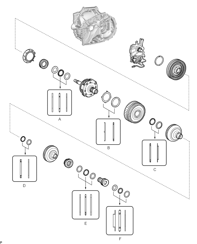
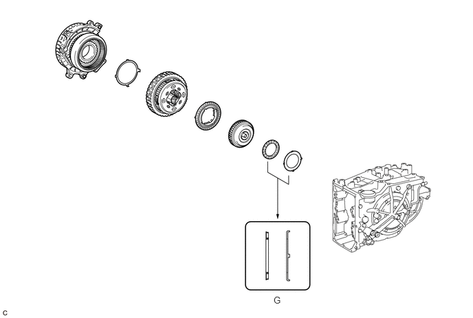
- Thrust Needle Roller Bearing and Bearing Race Diameter:
Mark Front Side Thrust Bearing Race Diameter Inside / Outside
mm (in.)Thrust Bearing Diameter Inside / Outside
mm (in.)Rear Side Thrust Bearing Race Diameter Inside / Outside
mm (in.)A 29.9 (1.18) / 49.5 (1.95) 28.7 (1.13) / 48 (1.89) 28.7 (1.13) / 48 (1.89) B 58.8 (2.31) / 71.4 (2.81) 57.3 (2.26) / 70.94 (2.79) - C - 35.2 (1.39) / 49.2 (1.94) 34.3 (1.35) / 46 (1.81) D - 37.6 (1.48) / 48.73 (1.92) 38.9 (1.53) / 50.3 (1.98) E 32 (1.26) / 43.5 (1.71) 31 (1.22) / 42.5 (1.67) 31 (1.22) / 42.5 (1.67) F 23.3 (0.917) / 39.8 (1.57) 22 (0.866) / 40.29 (1.59) 22 (0.866) / 39.8 (1.57) G - 47.5 (1.87) / 63.9 (2.52) 49.6 (1.95) / 68.7 (2.70)
35101E
2.INSTALL AUTOMATIC TRANSMISSION CASE STRAIGHT PIN
- NOTICE:
-
It is not necessary to remove the automatic transmission case straight pins unless they are being replaced.
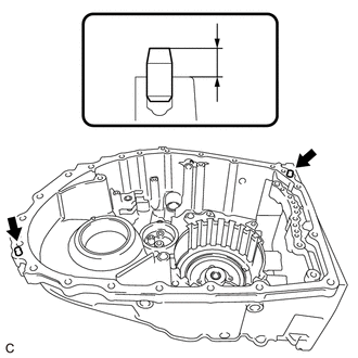
Using a plastic-faced hammer, tap in 2 new automatic transmission case straight pins to the specified protrusion height.
- Protrusion Height:
10.7 to 11.3 mm (0.421 to 0.445 in.)
3.INSTALL FRONT DIFFERENTIAL CASE FRONT TAPERED ROLLER BEARING (INNER RACE)
4.INSTALL FRONT DIFFERENTIAL CASE FRONT TAPERED ROLLER BEARING (OUTER RACE)
5.INSTALL FRONT DIFFERENTIAL CASE REAR TAPERED ROLLER BEARING (INNER RACE)
6.INSTALL FRONT DIFFERENTIAL CASE REAR TAPERED ROLLER BEARING (OUTER RACE)
7.INSTALL COUNTER DRIVEN GEAR FRONT TAPERED ROLLER BEARING (INNER RACE)
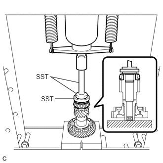
Using SST and a press, install a new counter driven gear front tapered roller bearing (inner race) to the pinion and counter driven gear sub-assembly.
- SST
- 09506-35010
09950-60011 (09951-00550)
09950-70010 (09951-07150)
- NOTICE:
-
Be sure to install the counter driven gear front tapered roller bearing (inner race) so that there is no clearance between the counter driven gear front tapered roller bearing (inner race) and the pinion and counter driven gear sub-assembly. If there is any clearance, the turning torque of the pinion and counter driven gear sub-assembly cannot be measured correctly.
8.INSTALL COUNTER DRIVEN GEAR FRONT TAPERED ROLLER BEARING (OUTER RACE)
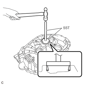
Using SST and a hammer, install a new counter driven gear front tapered roller bearing (outer race) and pinion and counter driven gear shim to the transaxle housing.
- SST
- 09950-60021 (09951-00720)
09950-70010 (09951-07150)
- NOTICE:
-
Be sure to install the counter driven gear front tapered roller bearing (outer race) so that there is no clearance between the counter driven gear front tapered roller bearing (outer race), pinion and counter driven gear shim and the transaxle housing. If there is any clearance, the turning torque of the pinion and counter driven gear sub-assembly cannot be measured correctly.
9.INSTALL COUNTER DRIVEN GEAR REAR TAPERED ROLLER BEARING (INNER RACE)
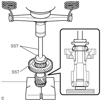
Using SST and a press, install a new counter driven gear rear tapered roller bearing (inner race) to the pinion and counter driven gear sub-assembly.
- SST
- 09506-30012
09950-60011 (09951-00420, 09951-00550)
09950-70010 (09951-07150)
- NOTICE:
-
Be sure to install the counter driven gear rear tapered roller bearing (inner race) so that there is no clearance between the counter driven gear rear tapered roller bearing (inner race) and the pinion and counter driven gear sub-assembly. If there is any clearance, the turning torque of the pinion and counter driven gear sub-assembly cannot be measured correctly.
10.INSTALL COUNTER DRIVEN GEAR REAR TAPERED ROLLER BEARING (OUTER RACE)
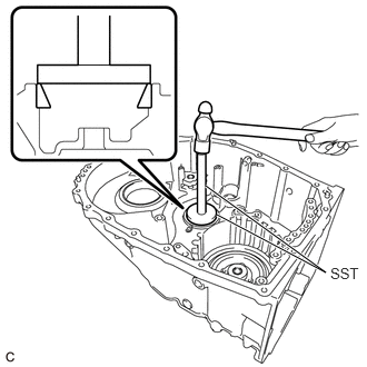
Using SST and a hammer, install a new counter driven gear rear tapered roller bearing (outer race) to the automatic transaxle case sub-assembly.
- SST
- 09950-60021 (09951-00680)
09950-70010 (09951-07150)
- NOTICE:
-
Be sure to install the counter driven gear rear tapered roller bearing (outer race) so that there is no clearance between the counter driven gear rear tapered roller bearing (outer race) and the automatic transaxle case sub-assembly. If there is any clearance, the turning torque of the pinion and counter driven gear sub-assembly cannot be measured correctly.
11.ADJUST FRONT DIFFERENTIAL CASE TAPERED ROLLER BEARING PRELOAD
Remove any remaining seal packing from the contact surfaces of the transaxle housing and automatic transaxle case sub-assembly.
Coat the front differential case front tapered roller bearing (inner race) and the front differential case rear tapered roller bearing (inner race) with a sufficient amount of Toyota Genuine ATF WS.
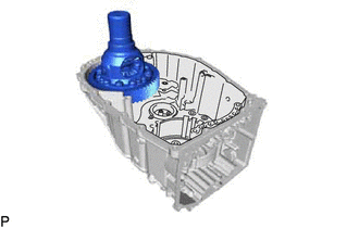
Install the differential case assembly to the automatic transaxle case sub-assembly.
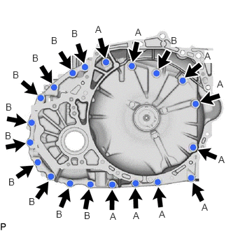
Install the transaxle housing to the automatic transaxle case sub-assembly with the 9 bolts (A) and 11 bolts (B).
- Torque:
- 29.4 N*m (300 kgf*cm, 22 ft.*lbf)
- Bolt Length:
Bolt (A) Bolt (B) 40 mm (1.57 in.) 35 mm (1.38 in.)
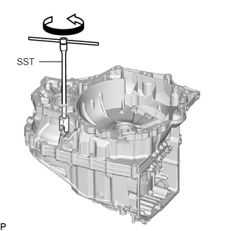
Using SST, rotate the differential case assembly 20 times or more to stabilize the bearing.
- SST
- 09564-33010
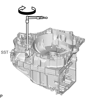
Using SST and a torque wrench, measure the turning torque of the front differential case tapered roller bearing while rotating SST at 10 rpm.
- SST
- 09564-33010
- Standard Turning Torque:
0.97 to 1.13 N*m (10 to 11 kgf*cm, 9 to 10 in.*lbf)
If the turning torque is not within the specified range, refer to the table below to select a shim so that the turning torque is within the specified range.
- Differential Drive Pinion Shim Thickness:
Part Number Thickness
mm (in.)Mark 90564-75002 1.10 (0.0433) 50 90564-75003 1.13 (0.0445) 51 90564-75004 1.16 (0.0457) 52 90564-75005 1.19 (0.0469) 53 90564-75006 1.22 (0.0480) 54 90564-75007 1.25 (0.0492) 55 90564-75008 1.28 (0.0504) 56 90564-75009 1.31 (0.0516) 57 90564-75010 1.34 (0.0528) 58 90564-75011 1.37 (0.0539) 59 90564-75012 1.40 (0.0551) 60 90564-75013 1.43 (0.0563) 61 90564-75014 1.46 (0.0575) 62 90564-75015 1.49 (0.0587) 63 90564-75016 1.52 (0.0598) 64 90564-75017 1.55 (0.0610) 65 90564-75018 1.58 (0.0622) 66 90564-75019 1.61 (0.0634) 67 90564-75023 1.64 (0.0646) 68 90564-75024 1.67 (0.0657) 69 90564-75025 1.70 (0.0669) 70 90564-75026 1.73 (0.0681) 71 90564-75027 1.76 (0.0693) 72 90564-75028 1.79 (0.0705) 73 90564-75029 1.82 (0.0717) 74 90564-75030 1.85 (0.0728) 75 90564-75031 1.88 (0.0740) 76 90564-75032 1.91 (0.0752) 77 90564-75033 1.94 (0.0764) 78 90564-75034 1.97 (0.0776) 79 90564-75035 2.00 (0.0787) 80
Remove the 20 bolts and transaxle housing from the automatic transaxle case sub-assembly.
12.ADJUST COUNTER DRIVEN GEAR TAPERED ROLLER BEARING PRELOAD
Coat the counter driven gear front tapered roller bearing (inner race) and the counter driven gear rear tapered roller bearing (inner race) with a sufficient amount of Toyota Genuine ATF WS.
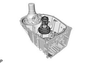
Install the pinion and counter driven gear sub-assembly to the automatic transaxle case sub-assembly.
Install the transaxle housing to the automatic transaxle case sub-assembly with the 9 bolts (A) and 11 bolts (B).
- Torque:
- 29.4 N*m (300 kgf*cm, 22 ft.*lbf)
- Bolt Length:
Bolt (A) Bolt (B) 40 mm (1.57 in.) 35 mm (1.38 in.)
Using SST, rotate the differential case assembly 20 times or more to stabilize the bearing.
- SST
- 09564-33010
Using SST and a torque wrench, measure the turning torque of the pinion and counter driven gear tapered roller bearing while rotating SST at 10 rpm.
- SST
- 09564-33010
- Standard Turning Torque:
Front differential case tapered roller bearing preload + 0.80 to 1.95 N*m (9 to 19 kgf*cm, 8 to 17 in.*lbf)
If the turning torque is not within the specified range, refer to the table below to select a shim so that the turning torque is within the specified range.
- Pinion and Counter Driven Gear Shim Thickness:
Part Number Thickness
mm (in.)Mark 90564-61146 1.18 (0.0465) AA 90564-61147 1.21 (0.0476) AB 90564-61127 1.24 (0.0488) AC 90564-61128 1.27 (0.0500) AD 90564-61129 1.30 (0.0512) AE 90564-61130 1.33 (0.0524) AF 90564-61131 1.36 (0.0535) AG 90564-61132 1.39 (0.0547) AH 90564-61133 1.42 (0.0559) AJ 90564-61134 1.45 (0.0571) AK 90564-61135 1.48 (0.0583) AL 90564-61136 1.51 (0.0594) AM 90564-61137 1.54 (0.0606) AN 90564-61138 1.57 (0.0618) AP 90564-61139 1.60 (0.0630) AR 90564-61140 1.63 (0.0642) AS 90564-61141 1.66 (0.0654) AT 90564-61142 1.69 (0.0665) AU 90564-61143 1.72 (0.0677) AV 90564-61144 1.75 (0.0689) AW 90564-61145 1.78 (0.0701) AX 90564-61148 1.81 (0.0713) AY 90564-61149 1.84 (0.0724) AZ 90564-61150 1.87 (0.0736) BA 90564-61151 1.90 (0.0748) BB 90564-61152 1.93 (0.0760) BC 90564-61153 1.96 (0.0772) BD 90564-61154 1.99 (0.0783) BE 90564-61155 2.02 (0.0795) BF 90564-61156 2.05 (0.0807) BG 90564-61157 2.08 (0.0819) BH 90564-61158 2.11 (0.0831) BJ 90564-61159 2.14 (0.0843) BK 90564-61160 2.17 (0.0854) BL 90564-61161 2.20 (0.0866) BM
Remove the 20 bolts and transaxle housing from the automatic transaxle case sub-assembly.
Remove the pinion and counter driven gear sub-assembly from the automatic transaxle case sub-assembly.
Remove the differential case assembly from the automatic transaxle case sub-assembly.
35104R
13.INSTALL NO. 2 TRANSAXLE CASE PLUG
Clean the 6 No. 2 transaxle case plugs and 6 installation holes.
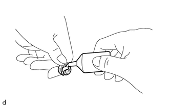
Apply adhesive to 2 or 3 threads on the ends of the No. 2 transaxle case plugs.
- Adhesive:
Toyota Genuine Adhesive 1324, Three Bond 1324 or equivalent
- NOTICE:
-
Make sure to install the No. 2 transaxle case plugs immediately after applying adhesive to prevent foreign matter from attaching to them.
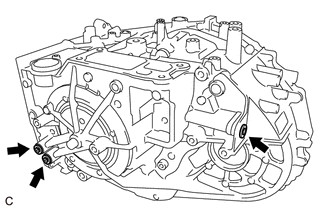
Using a 6 mm socket hexagon wrench, install the 3 No. 2 transaxle case plugs and 3 new gaskets to the automatic transaxle case sub-assembly.
- Torque:
- 17 N*m (173 kgf*cm, 13 ft.*lbf)
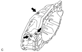
Using a 6 mm socket hexagon wrench, install the 3 No. 2 transaxle case plugs and 3 new gaskets to the transaxle housing.
- Torque:
- 17 N*m (173 kgf*cm, 13 ft.*lbf)
35104Q
14.INSTALL NO. 1 TRANSAXLE CASE PLUG
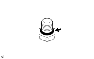
Coat 8 new O-rings with Toyota Genuine ATF WS and install them to the 8 No. 1 transaxle case plugs.
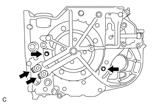
Install the 4 No. 1 transaxle case plugs to the automatic transaxle case sub-assembly.
- Torque:
- 7.4 N*m (75 kgf*cm, 65 in.*lbf)
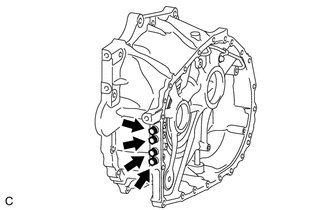
Install the 4 No. 1 transaxle case plugs to the transaxle housing.
- Torque:
- 7.4 N*m (75 kgf*cm, 65 in.*lbf)
35605C
15.INSTALL NEEDLE ROLLER BEARING
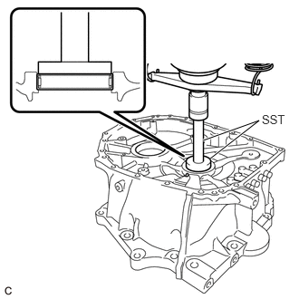
Using SST and a press, install a new needle roller bearing to the transaxle housing.
- SST
- 09950-60011 (09951-00560)
09950-70010 (09951-07200)
- NOTICE:
-
Be careful not to damage the transaxle housing.
43420H
16.INSTALL FRONT DRIVE SHAFT OIL SEAL LH
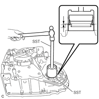
Using SST and a hammer, install a new front drive shaft oil seal LH to the automatic transaxle case sub-assembly.
- SST
- 09649-17010
09950-70010 (09951-07200)
- Standard Depth:
-0.5 to 0.5 mm (-0.0197 to 0.0197 in.)
17.INSTALL TRANSAXLE CASE OIL SEAL
Clean and degrease the oil seal press-in surface.
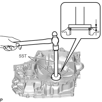
Using SST and a hammer, install a new transaxle case oil seal to the transaxle housing.
- SST
- 09950-60011 (09951-00640)
09950-70010 (09951-07200)
- Standard Depth:
-0.5 to 0.5 mm (-0.0197 to 0.0197 in.)
Apply MP grease to the lip of the transaxle case oil seal.
18.INSTALL MANUAL VALVE LEVER SHAFT OIL SEAL
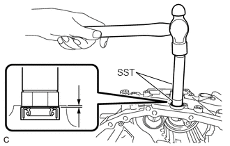
Using SST and a hammer, install a new manual valve lever shaft oil seal to the automatic transaxle case sub-assembly.
- SST
- 09950-60011 (09951-00210)
09950-70010 (09951-07200)
- Standard Depth:
-0.3 to 0.4 mm (-0.0118 to 0.0157 in.)
Apply MP grease to the lip of the manual valve lever shaft oil seal.
35623H
19.INSTALL 1ST AND REVERSE BRAKE PISTON
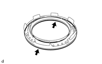
Apply a light coat of Toyota Genuine ATF WS to 2 new O-rings and install them to the 1st and reverse brake piston.
- NOTICE:
- ·
Make sure to correctly distinguish between the inner side and outer side O-rings.
·Be careful not to damage or twist the O-rings.
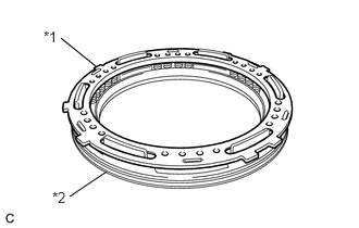
| *1 | 1st And Reverse Brake Return Spring Sub-assembly |
| *2 | 1st And Reverse Brake Piston |
Set the 1st and reverse brake return spring sub-assembly on the 1st and reverse brake piston.
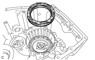
Install the 1st and reverse brake piston with 1st and reverse brake return spring sub-assembly to the automatic transaxle case sub-assembly.
- NOTICE:
-
Make sure that the O-rings are not damaged or do not jump out of position during installation.
35068
20.INSTALL 1ST AND REVERSE BRAKE RETURN SPRING SUB-ASSEMBLY
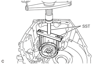
Place SST on the 1st and reverse brake return spring sub-assembly and compress it with a press.
- SST
- 09380-60012 (09381-06020, 09381-06050, 09381-06070)
09950-70010 (09951-07200)
- NOTICE:
-
Stop the press when the 1st and reverse brake return spring sub-assembly is flush with the snap ring groove.
Using a screwdriver with its tip wrapped with protective tape, set the snap ring on the automatic transaxle case sub-assembly as shown in the illustration.
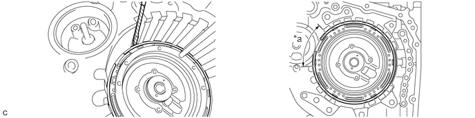
| *a | Snap ring opening within this area. | - | - |
- NOTICE:
-
The opening of the snap ring should be within the area shown in the illustration (spline portion).
Using a screwdriver with its tip wrapped with protective tape, install the snap ring into the snap ring groove of the automatic transaxle case sub-assembly.
- NOTICE:
- ·
Be careful not to damage the automatic transaxle case sub-assembly.
·Make sure that the snap ring is installed in the groove of the automatic transaxle case sub-assembly correctly.
35623P
21.INSTALL NO. 2 1ST AND REVERSE BRAKE PISTON
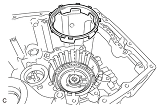
Install the No. 2 1st and reverse brake piston to the automatic transaxle case sub-assembly.
35682
22.INSTALL 2ND BRAKE BRAKE DISC
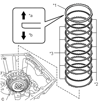
| *1 | 2nd Brake Brake Flange |
| *2 | 2nd Brake Brake Disc |
| *3 | 2nd Brake Brake Plate |
| *a | Snap Ring Side |
| *b | 2nd Brake Brake Disc Side |
Install the 5 2nd brake brake plates, 5 2nd brake brake discs and 2nd brake brake flange to the automatic transaxle case sub-assembly.
- NOTICE:
-
Assemble the 2nd brake brake flange with its tapered surface facing toward the 2nd brake brake disc.
Using a screwdriver with its tip wrapped with protective tape, install the snap ring to the automatic transaxle case sub-assembly.
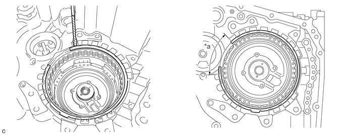
| *a | Snap ring opening within this area. | - | - |
- NOTICE:
-
The opening of the snap ring should be within the area shown in the illustration (spline portion).
23.INSPECT CLEARANCE OF B-2 BRAKE
35653B
24.INSTALL DIRECT CLUTCH DRUM OIL SEAL RING
Apply a small amount of MP grease to the entire circumference of the direct clutch drum oil seal ring installation groove portion.
- HINT:
-
By applying MP grease, the wobble within the direct clutch drum oil seal ring installation groove will be eliminated, preventing damage to the direct clutch drum oil seal ring at the time of front planetary gear assembly installation.
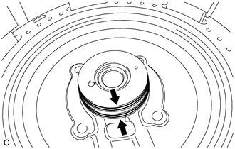
Coat 2 new direct clutch drum oil seal rings with Toyota Genuine ATF WS and install them to the automatic transaxle case sub-assembly.
- NOTICE:
-
While making the spread of the opening of the direct clutch drum oil seal ring as small as possible, install it to the automatic transaxle case sub-assembly. If the ring opening is spread, briefly hold it closed with your fingers to return it to its original condition.
35652E
25.INSTALL C-2 CLUTCH PISTON
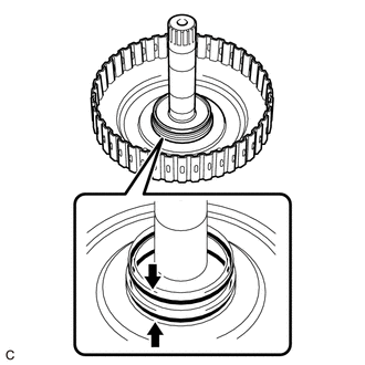
Apply a light coat of Toyota Genuine ATF WS to 2 new O-rings and install them to the intermediate shaft sub-assembly.
- NOTICE:
-
Be careful not to damage or twist the O-ring.
Apply a light coat of Toyota Genuine ATF WS to the lip seal of the C-2 clutch piston.
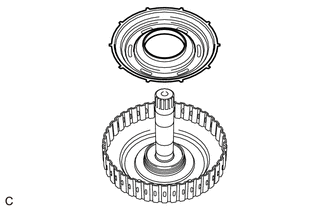
Install the C-2 clutch piston to the intermediate shaft sub-assembly.
- NOTICE:
- ·
Make sure the lip is not cut or folded.
·Be careful not to damage the lip seal of the C-2 clutch piston.
35608N
26.INSTALL CLUTCH RETURN SPRING SUB-ASSEMBLY
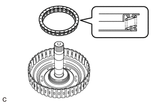
Install the clutch return spring sub-assembly to the intermediate shaft sub-assembly.
35698A
27.INSTALL C-2 CLUTCH BALANCER
Apply a light coat of Toyota Genuine ATF WS to the lip seal of the C-2 clutch balancer.
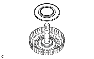
Install the C-2 clutch balancer to the intermediate shaft sub-assembly.
- NOTICE:
- ·
Make sure the lip is not cut or folded.
·Be careful not to damage the lip seal of the C-2 clutch balancer.
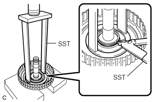
Place SST on the C-2 clutch balancer and compress the clutch return spring sub-assembly with a press.
- SST
- 09387-00020
- NOTICE:
-
Stop the press when the clutch return spring sub-assembly is flush with the snap ring groove.
Using SST, install the snap ring to the intermediate shaft sub-assembly.
- SST
- 09350-30020 (09350-07070)
- NOTICE:
-
Make sure that the snap ring is installed in the groove of the intermediate shaft sub-assembly correctly.
35667B
28.INSTALL NO. 2 CLUTCH DISC
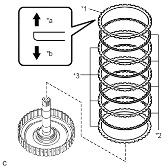
| *1 | Direct Clutch Flange |
| *2 | No. 2 Clutch Disc |
| *3 | No. 2 Clutch Plate |
| *a | Snap Ring Side |
| *b | No. 2 Clutch Disc Side |
Install the 4 No. 2 clutch plates, 4 No. 2 clutch discs and direct clutch flange to the intermediate shaft sub-assembly.
- NOTICE:
-
Assemble the direct clutch flange with its tapered surface facing toward the No. 2 clutch disc.
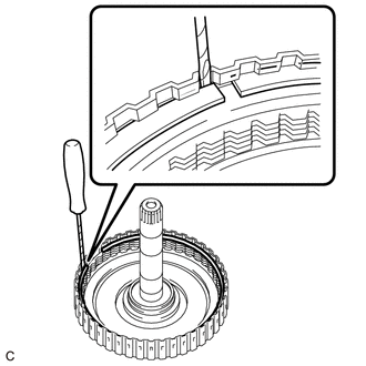
Using a screwdriver with its tip wrapped in protective tape, install the snap ring to the intermediate shaft sub-assembly.
- NOTICE:
- ·
Be careful not to damage the intermediate shaft sub-assembly.
·Make sure that the snap ring is installed in the groove of the intermediate shaft sub-assembly correctly.
35786A
29.INSTALL NO. 1 THRUST BEARING RACE
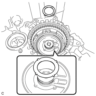
Coat the No. 1 thrust bearing race with Toyota Genuine ATF WS and install it to the automatic transaxle case sub-assembly.
- No. 1 Thrust Bearing Race Diameter:
Inside
mm (in.)Outside
mm (in.)49.6 (1.95) 68.7 (2.70)
- NOTICE:
-
Securely insert the claw of the No. 1 thrust bearing race into the hole of the automatic transaxle case sub-assembly.
30.INSTALL THRUST NEEDLE ROLLER BEARING
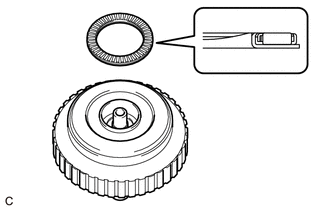
Coat the thrust needle roller bearing with Toyota Genuine ATF WS and install it to the C-2 clutch assembly.
- Thrust Needle Roller Bearing Diameter:
Inside
mm (in.)Outside
mm (in.)47.5 (1.87) 63.9 (2.52)
- NOTICE:
-
Make sure to assemble the thrust needle roller bearing in the correct direction.
31.INSTALL C-2 CLUTCH ASSEMBLY
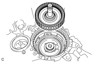
Install the C-2 clutch assembly to the automatic transaxle case sub-assembly.
- HINT:
-
When installing the C-2 clutch assembly, if the thrust needle roller bearing falls off, coat the C-2 clutch assembly installation surface with MP grease and install the parts.
32.INSPECT CLEARANCE OF C-2 CLUTCH
35787C
33.INSTALL NO. 2 THRUST BEARING RACE
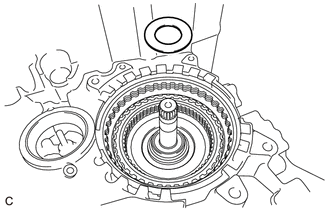
Coat the No. 2 thrust bearing race with Toyota Genuine ATF WS and install it to the C-2 clutch assembly.
- No. 2 Thrust Bearing Race Diameter:
Inside
mm (in.)Outside
mm (in.)22 (0.866) 39.8 (1.57)
34.INSTALL THRUST NEEDLE ROLLER BEARING
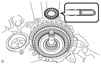
Coat the thrust needle roller bearing with Toyota Genuine ATF WS and install it to the C-2 clutch assembly.
- Thrust Needle Roller Bearing Diameter:
Inside
mm (in.)Outside
mm (in.)22 (0.866) 40.29 (1.59)
35729B
35.INSTALL NO. 4 PLANETARY CARRIER THRUST WASHER
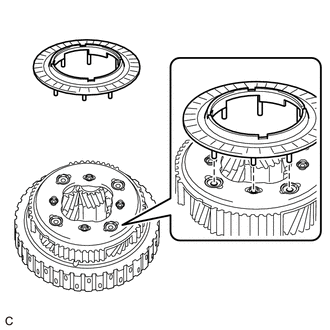
Install the No. 4 planetary carrier thrust washer to the rear planetary gear assembly.
- HINT:
-
Securely insert each protrusion of the No. 4 planetary carrier thrust washer into each indentation of the rear planetary gear assembly.
35760
36.INSTALL REAR PLANETARY GEAR ASSEMBLY
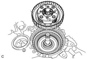
Install the rear planetary gear assembly to the C-2 clutch assembly.
- HINT:
-
When installing the rear planetary gear assembly, if the No. 4 planetary carrier thrust washer falls off, coat the rear planetary gear assembly installation surface with MP grease and install the parts.
35739
37.INSTALL NO. 3 PLANETARY CARRIER THRUST WASHER
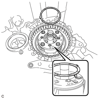
Coat the No. 3 planetary carrier thrust washer with Toyota Genuine ATF WS and install it to the rear planetary gear assembly.
- NOTICE:
-
Securely insert the claw of the No. 3 planetary carrier thrust washer into the hole of the rear planetary gear assembly.
38.INSTALL NO. 1 BRAKE DISC
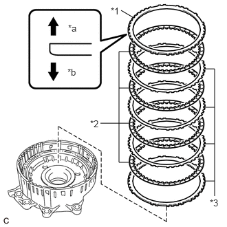
| *1 | No. 1 Brake Flange |
| *2 | No. 1 Brake Disc |
| *3 | No. 1 Brake Plate |
| *a | Snap Ring Side |
| *b | No. 1 Brake Disc Side |
Install the 4 No. 1 brake plates, 4 No. 1 brake discs and No. 1 brake flange to the counter drive gear sub-assembly.
- NOTICE:
- ·
Be careful during assembly because there are 2 types of No. 1 brake plates with different thicknesses.
·Assemble the No. 1 brake flange with its tapered surface facing toward the No. 1 brake disc.
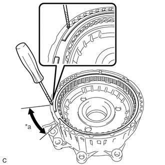
| *a | Snap ring opening within this area. |
Using a screwdriver with its tip wrapped in protective tape, install the snap ring to the counter drive gear sub-assembly.
- NOTICE:
- ·
Be careful not to damage the counter drive gear sub-assembly.
·Make sure that the snap ring is installed in the groove of the counter drive gear sub-assembly correctly.
·The opening of the snap ring should be within the area shown in the illustration (spline portion).
39.INSTALL COUNTER DRIVE GEAR SUB-ASSEMBLY
Clean and degrease the counter drive gear sub-assembly installation bolts and the 7 bolt holes.
- NOTICE:
-
If the bolts are tightened without cleaning and degreasing the bolts and bolt holes, the tightening torque will be too high and the counter drive gear sub-assembly or automatic transaxle case sub-assembly may be damaged.
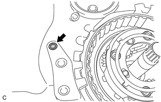
Coat a new O-ring with Toyota Genuine ATF WS and install it to the automatic transaxle case sub-assembly.
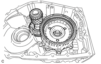
Install the counter drive gear sub-assembly together with the pinion and counter driven gear sub-assembly to the automatic transaxle case sub-assembly.
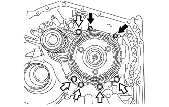

|
"TORX" Bolt |

|
Bolt |
Temporarily install the 2 "TORX" bolts and 5 bolts.
Tighten the 5 bolts.
- Torque:
- 76 N*m (775 kgf*cm, 56 ft.*lbf)
Using a T50 "TORX" socket wrench, tighten the 2 "TORX" bolts.
- Torque:
- 31.8 N*m (324 kgf*cm, 23 ft.*lbf)
40.INSPECT CLEARANCE OF B-1 BRAKE
35598
41.INSTALL PARKING LOCK SLEEVE
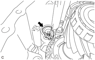
Coat the parking lock sleeve with Toyota Genuine ATF WS and install it to the automatic transaxle case sub-assembly.
35557
42.INSTALL PARKING LOCK PAWL
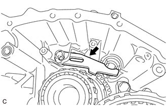
Coat the parking lock pawl with Toyota Genuine ATF WS and install it to the automatic transaxle case sub-assembly.
35556
43.INSTALL PARKING LOCK PAWL SHAFT
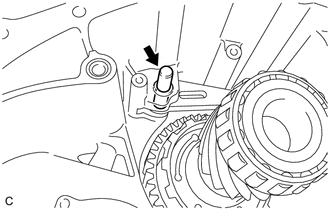
Coat the parking lock pawl shaft with Toyota Genuine ATF WS and install it to the automatic transaxle case sub-assembly.
35557A
44.INSTALL PARKING LOCK PAWL TORSION SPRING
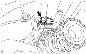
Install the parking lock pawl torsion spring to the automatic transaxle case sub-assembly as shown in the illustration.
- NOTICE:
-
Securely insert the parking lock pawl torsion spring all the way into the parking lock pawl shaft.
35506
45.INSTALL MANUAL VALVE LEVER SHAFT SUB-ASSEMBLY
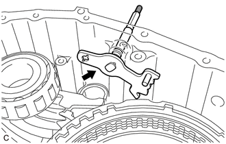
Install the manual valve lever shaft sub-assembly to the automatic transaxle case sub-assembly.
- NOTICE:
-
When installing the manual valve lever shaft sub-assembly, be careful not to damage the manual valve lever shaft oil seal.
35501
46.INSTALL PARKING LOCK ROD SUB-ASSEMBLY
Install the parking lock rod sub-assembly as shown in the illustration.
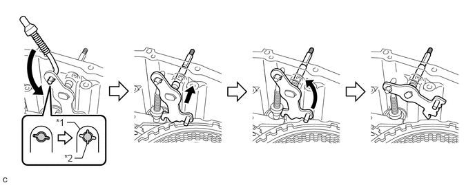
| *1 | Manual Valve Lever Shaft Sub-assembly | *2 | Parking Lock Rod Sub-assembly |
- NOTICE:
-
Securely align the cutouts of the parking lock rod sub-assembly and manual valve lever shaft sub-assembly.
35506J
47.INSTALL MANUAL VALVE LEVER SHAFT RETAINER SPRING
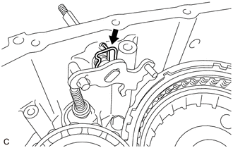
Install the manual valve lever shaft retainer spring to the automatic transaxle case sub-assembly.
35596
48.INSTALL PAWL STOPPER PLATE
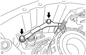
Install the pawl stopper plate to the automatic transaxle case sub-assembly with the 2 bolts.
- Torque:
- 9.8 N*m (100 kgf*cm, 87 in.*lbf)
35505
49.INSTALL MANUAL VALVE LEVER SUB-ASSEMBLY
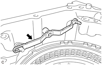
Install the manual valve lever sub-assembly to the automatic transaxle case sub-assembly.
- NOTICE:
-
The pin portion of the manual valve lever shaft sub-assembly must be inserted into the slot of the manual valve lever sub-assembly.
35506
50.INSTALL MANUAL VALVE LEVER SHAFT SUB-ASSEMBLY
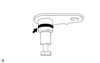
Coat a new O-ring with Toyota Genuine ATF WS and install it to the manual valve lever shaft sub-assembly.
- NOTICE:
-
Ensure that the O-ring is not twisted.
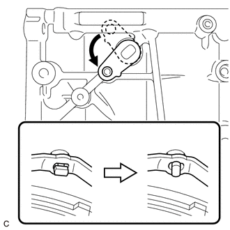
Align the cutouts of the manual valve lever sub-assembly and manual valve lever shaft sub-assembly, and install the manual valve lever shaft sub-assembly.
- HINT:
-
Installing the manual valve lever shaft sub-assembly to the area shown in the illustration will align the cutouts.
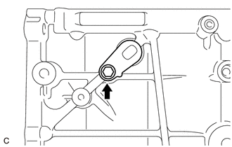
Secure the manual valve lever shaft sub-assembly to the automatic transaxle case sub-assembly with the bolt.
- Torque:
- 9.8 N*m (100 kgf*cm, 87 in.*lbf)
35612B
51.INSTALL FORWARD CLUTCH PISTON
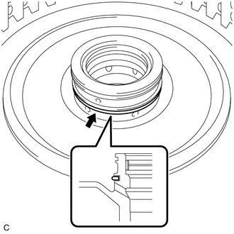
Apply a light coat of Toyota Genuine ATF WS to a new D-ring and install it to the clutch drum sub-assembly.
- HINT:
- ·
Be careful not to damage or twist the D-ring.
·The rounded surface of the D-ring will be on the outer side of the ring groove.
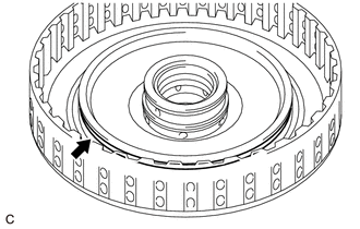
Apply a light coat of Toyota Genuine ATF WS to a new O-ring and install it to the clutch drum sub-assembly.
- NOTICE:
-
Be careful not to damage or twist the O-ring.
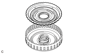
Apply a light coat of Toyota Genuine ATF WS to the forward clutch piston and install it to the clutch drum sub-assembly.
- NOTICE:
- ·
Make sure that the O-ring and D-ring are not damaged or do not jump out of position during installation.
·Make sure the lip is not cut or folded.
35650B
52.INSTALL REAR CLUTCH PISTON RETURN COMPRESSION SPRING
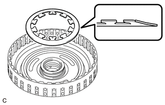
Install the rear clutch piston return compression spring to the forward clutch piston.
- NOTICE:
-
Make sure to install in the correct direction.
35668
53.INSTALL NO. 1 CLUTCH BALANCER
Apply a light coat of Toyota Genuine ATF WS to the lip seal of the forward clutch piston.
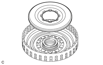
Install the No. 1 clutch balancer to the forward clutch piston.
- NOTICE:
-
Be careful not to damage the lip seal of the forward clutch piston.
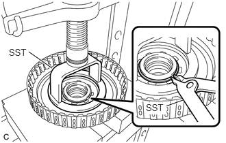
Place SST on the No. 1 clutch balancer and compress the rear clutch piston return compression spring with a press.
- SST
- 09320-89010
- NOTICE:
-
Stop the press when the rear clutch piston return compression spring is flush with the snap ring groove.
Using SST, install the snap ring to the clutch drum sub-assembly.
- SST
- 09350-30020 (09350-07070)
- NOTICE:
-
Make sure that the snap ring is installed in the groove of the clutch drum sub-assembly correctly.
35633
54.INSTALL FRONT CLUTCH CLUTCH DISC
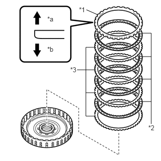
| *1 | Forward Clutch Flange |
| *2 | Front Clutch Clutch Disc |
| *3 | Forward Multiple Disc Clutch Clutch Plate |
| *a | Snap Ring Side |
| *b | Front Clutch Clutch Disc Side |
Install the 4 forward multiple disc clutch clutch plates, 4 front clutch clutch discs and forward clutch flange to the clutch drum sub-assembly.
- NOTICE:
-
Assemble the forward clutch flange with its tapered surface facing toward the front clutch clutch disc.
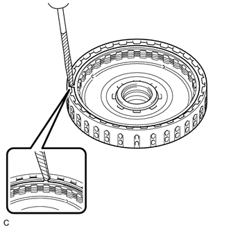
Using a screwdriver with its tip wrapped in protective tape, install the snap ring to the clutch drum sub-assembly.
- NOTICE:
- ·
Be careful not to damage the clutch drum sub-assembly.
·Make sure that the snap ring is installed in the groove of the clutch drum sub-assembly correctly.
55.INSTALL TOLERANCE RING
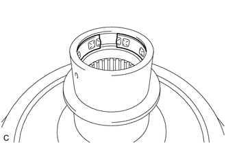
Install a new tolerance ring to the clutch drum sub-assembly.
35775K
56.INSTALL NO. 5 THRUST BEARING RACE
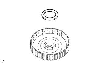
Coat the No. 5 thrust bearing race with Toyota Genuine ATF WS and install it to the sun gear input hub sub-assembly.
- No. 5 Thrust Bearing Race Diameter:
Inside
mm (in.)Outside
mm (in.)38.9 (1.53) 50.3 (1.98)
57.INSTALL THRUST NEEDLE ROLLER BEARING
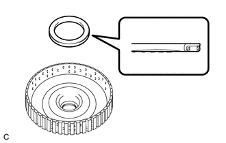
Coat the thrust needle roller bearing with Toyota Genuine ATF WS and install it to the sun gear input hub sub-assembly.
- Thrust Needle Roller Bearing Diameter:
Inside
mm (in.)Outside
mm (in.)37.6 (1.48) 48.73 (1.92)
58.INSTALL C-1 CLUTCH ASSEMBLY
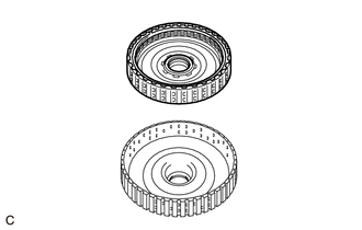
Install the C-1 clutch assembly to the sun gear input hub sub-assembly.
35707D
59.INSTALL REAR PLANETARY SUN GEAR SUB-ASSEMBLY
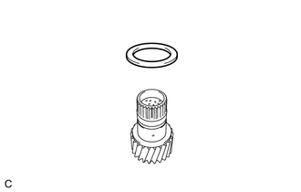
Coat the thrust bearing race with Toyota Genuine ATF WS and install it to the rear planetary sun gear sub-assembly.
- Thrust Bearing Race Diameter:
Inside
mm (in.)Outside
mm (in.)31 (1.22) 42.5 (1.67)
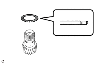
Coat the thrust needle roller bearing with Toyota Genuine ATF WS and install it to the rear planetary sun gear sub-assembly.
- Thrust Needle Roller Bearing Diameter:
Inside
mm (in.)Outside
mm (in.)31 (1.22) 42.5 (1.67)
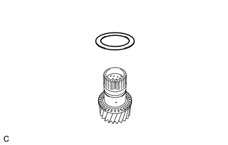
Coat the No. 4 thrust bearing race with Toyota Genuine ATF WS and install it to the rear planetary sun gear sub-assembly.
- No. 4 Thrust Bearing Race Diameter:
Inside
mm (in.)Outside
mm (in.)32 (1.26) 43.5 (1.71)
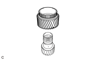
Install the planetary sun gear sub-assembly to the rear planetary sun gear sub-assembly.
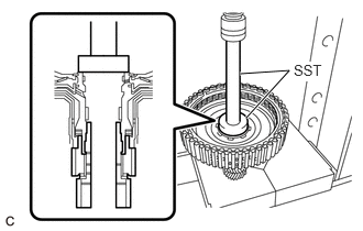
Using SST and a press, install the rear planetary sun gear sub-assembly to the C-1 clutch assembly.
- SST
- 09950-60011 (09951-00460)
09950-70010 (09951-07100)
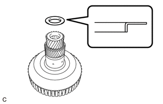
Coat the No. 3 thrust bearing race with Toyota Genuine ATF WS and install it to the rear planetary sun gear sub-assembly.
- No. 3 Thrust Bearing Race Diameter:
Inside
mm (in.)Outside
mm (in.)23.3 (0.917) 39.8 (1.57)
60.INSPECT CLEARANCE OF C-1 CLUTCH
61.INSTALL C-1 CLUTCH ASSEMBLY
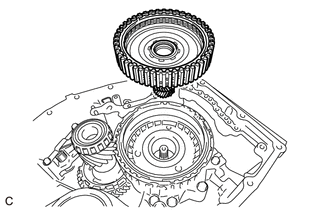
Install the C-1 clutch assembly to the counter drive gear sub-assembly.
- HINT:
-
When installing the C-1 clutch assembly, if the No. 3 thrust bearing race falls off, coat the rear planetary sun gear sub-assembly installation surface with MP grease and then install the parts.
35776
62.INSTALL NO. 6 THRUST BEARING RACE
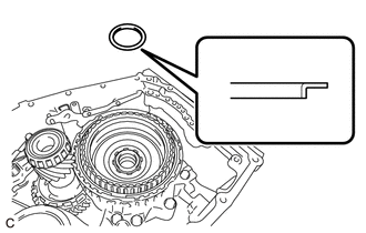
Coat the No. 6 thrust bearing race with Toyota Genuine ATF WS and install it to the C-1 clutch assembly.
- No. 6 Thrust Bearing Race Diameter:
Inside
mm (in.)Outside
mm (in.)34.3 (1.35) 46 (1.81)
63.INSTALL THRUST NEEDLE ROLLER BEARING
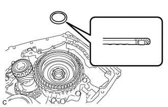
Coat the thrust needle roller bearing with Toyota Genuine ATF WS and install it to the C-1 clutch assembly.
- Thrust Needle Roller Bearing Diameter:
Inside
mm (in.)Outside
mm (in.)35.2 (1.39) 49.2 (1.94)
35743
64.INSTALL FRONT PLANETARY RING GEAR
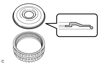
Install the front planetary ring gear flange to the front planetary ring gear.
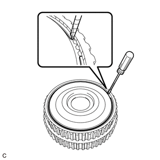
Using a screwdriver with its tip wrapped with protective tape, install the snap ring to the front planetary ring gear.
- NOTICE:
-
Be careful not to damage the front planetary ring gear and front planetary ring gear flange.
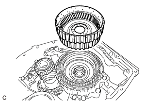
Install the front planetary ring gear with front planetary ring gear flange to the C-1 clutch assembly.
35749B
65.INSTALL REAR INPUT SHAFT OIL SEAL RING
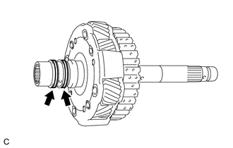
Apply a small amount of MP grease to the entire circumference of the rear input shaft oil seal ring installation groove portion.
- HINT:
-
By applying MP grease, the wobble within the rear input shaft oil seal ring installation groove will be eliminated, preventing damage to the rear input shaft oil seal ring at the time of front planetary gear assembly installation.
Coat 2 new rear input shaft oil seal rings with Toyota Genuine ATF WS and install them to the front planetary gear assembly.
- NOTICE:
-
While making the spread of the opening of the rear input shaft oil seal ring as small as possible, install it to the front planetary gear assembly. If the ring opening is spread, briefly hold it closed with your fingers to return it to its original condition.
35712E
66.INSTALL INPUT SHAFT OIL SEAL RING
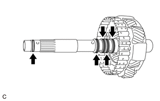
Apply a small amount of MP grease to the entire circumference of the input shaft oil seal ring installation groove portion.
- HINT:
-
By applying MP grease, the wobble within the input shaft oil seal ring installation groove will be eliminated, preventing damage to the input shaft oil seal ring at the time of the front oil pump assembly and torque converter assembly installation.
Coat 5 new input shaft oil seal rings with Toyota Genuine ATF WS and install them to the front planetary gear assembly.
- NOTICE:
-
While making the spread of the opening of the input shaft oil seal ring as small as possible, install it to the front planetary gear assembly. If the ring opening is spread, briefly hold it closed with your fingers to return it to its original condition.
35777
67.INSTALL NO. 7 THRUST BEARING RACE
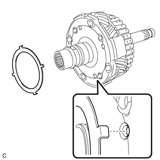
Coat the No. 7 thrust bearing race with Toyota Genuine ATF WS and install it to the front planetary gear assembly.
- No. 7 Thrust Bearing Race Diameter:
Inside
mm (in.)Outside
mm (in.)58.8 (2.31) 71.4 (2.81)
- NOTICE:
-
Securely insert the claw of the No. 7 thrust bearing race into the hole of the front planetary gear assembly.
68.INSTALL THRUST NEEDLE ROLLER BEARING
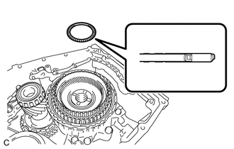
Coat the thrust needle roller bearing with Toyota Genuine ATF WS and install it to the front planetary ring gear.
- Thrust Needle Roller Bearing Diameter:
Inside
mm (in.)Outside
mm (in.)57.3 (2.26) 70.94 (2.79)
35720
69.INSTALL FRONT PLANETARY GEAR ASSEMBLY
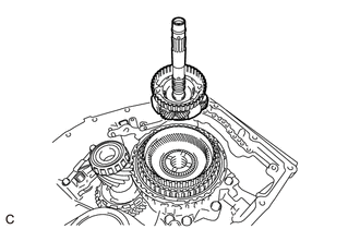
Install the front planetary gear assembly to the front planetary ring gear.
- HINT:
-
When installing the front planetary gear assembly, if the No. 7 thrust bearing race falls off, coat the front planetary gear assembly installation surface with MP grease and install the parts.
35778
70.INSTALL NO. 8 THRUST BEARING RACE
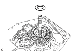
Coat the No. 8 thrust bearing race with Toyota Genuine ATF WS and install it to the front planetary gear assembly.
- No. 8 Thrust Bearing Race Diameter:
Inside
mm (in.)Outside
mm (in.)28.7 (1.13) 48 (1.89)
35778A
71.INSTALL THRUST NEEDLE ROLLER BEARING
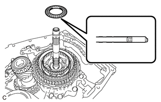
Coat the thrust needle roller bearing with Toyota Genuine ATF WS and install it to the front planetary gear assembly.
- Thrust Needle Roller Bearing Diameter:
Inside
mm (in.)Outside
mm (in.)28.7 (1.13) 48 (1.89)
35779A
72.INSTALL NO. 9 THRUST BEARING RACE
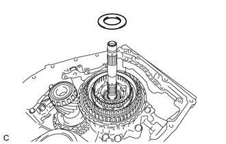
Coat the No. 9 thrust bearing race with Toyota Genuine ATF WS and install it to the front planetary gear assembly.
- No. 9 Thrust Bearing Race Diameter:
Inside
mm (in.)Outside
mm (in.)29.9 (1.18) 49.5 (1.95)
35719B
73.INSTALL PLANETARY SUN GEAR
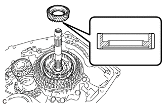
Install the planetary sun gear to the front planetary gear assembly.
35738
74.INSTALL NO. 2 PLANETARY CARRIER THRUST WASHER
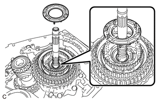
Install the No. 2 planetary carrier thrust washer to the front planetary gear assembly.
- NOTICE:
-
Securely insert each protrusion of the No. 2 planetary carrier thrust washer into each indentation of the front planetary gear assembly.
75.INSPECT CLEARANCE OF C-4 CLUTCH
76.INSPECT CLEARANCE OF C-3 CLUTCH
34610
77.INSTALL C-3 AND C-4 CLUTCH ASSEMBLY
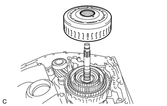
Install the C-3 and C-4 clutch assembly to the front planetary gear assembly.
35737
78.INSTALL PLANETARY CARRIER THRUST WASHER
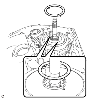
Install the planetary carrier thrust washer to the C-3 and C-4 clutch assembly.
- NOTICE:
-
Securely insert the protrusion of the planetary carrier thrust washer into the indentation of the C-3 and C-4 clutch assembly.
79.INSTALL FRONT OIL PUMP ASSEMBLY
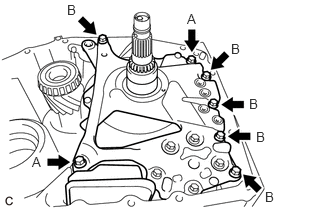
Install the front oil pump assembly to the automatic transaxle case sub-assembly with the 7 bolts.
- Torque:
- 24.5 N*m (250 kgf*cm, 18 ft.*lbf)
- Bolt Length:
Bolt (A) Bolt (B) 40 mm (1.57 in.) 30 mm (1.18 in.)
35409D
80.INSTALL MANUAL DETENT SPRING SUB-ASSEMBLY
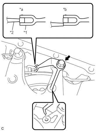
| *1 | Manual Detent Spring Sub-assembly |
| *2 | Manual Valve Lever Shaft Sub-assembly |
| *a | Correct |
| *b | Incorrect |
Install the manual detent spring sub-assembly to the front oil pump assembly with the bolt.
- Torque:
- 9.8 N*m (100 kgf*cm, 87 in.*lbf)
- NOTICE:
- ·
Securely insert the claw of the manual detent spring sub-assembly into the hole of the front oil pump assembly.
·Check that the roller portion of the manual detent spring sub-assembly is engaged with the manual valve lever shaft sub-assembly.
35355
81.INSTALL OIL PUMP SPROCKET REAR THRUST WASHER
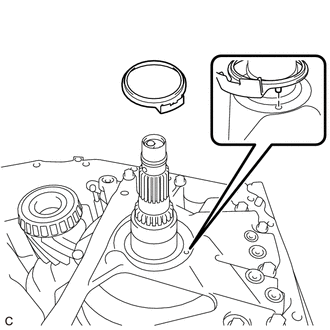
Install the oil pump sprocket rear thrust washer to the front oil pump assembly.
- NOTICE:
-
Securely insert the protrusion of the oil pump sprocket rear thrust washer into the indentation of the front oil pump assembly.
35781C
82.INSTALL TRANSMISSION DRIVE CHAIN
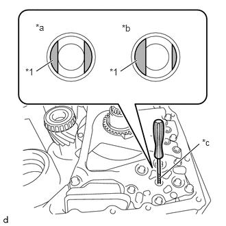
| *1 | Front Oil Pump Drive Gear |
| *a | Correct |
| *b | Incorrect |
| *c | Protective Tape |
Using a screwdriver with its tip wrapped in protective tape, align the cutout of the front oil pump drive gear with the position (*a) shown in the illustration.
- NOTICE:
-
Do not pry with excessive force when aligning the cutout of the front oil pump drive gear.
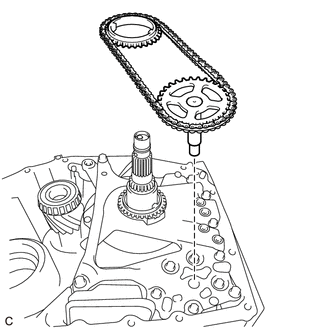
Install the transmission drive chain together with the transmission oil pump drive sprocket and oil pump drive shaft sub-assembly to the front oil pump assembly.
- NOTICE:
- ·
To avoid damaging the bush of the front oil pump assembly, install the transmission drive chain, transmission oil pump drive sprocket and oil pump drive shaft sub-assembly horizontally relative to the front oil pump assembly.
·Align the cutout of the oil pump drive shaft sub-assembly and the cutout of the front oil pump drive gear, and install the parts.
35354
83.INSTALL OIL PUMP SPROCKET FRONT THRUST WASHER
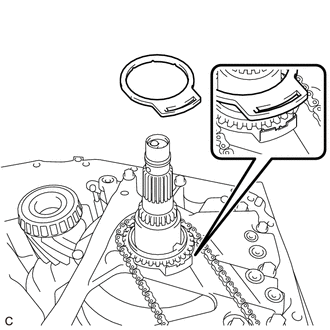
Install the oil pump sprocket front thrust washer to the transmission oil pump drive sprocket.
- NOTICE:
-
Securely insert the long protrusion of the oil pump sprocket rear thrust washer into the slot of the oil pump sprocket front thrust washer.
35617
84.INSTALL CLUTCH DRUM OIL SEAL RING
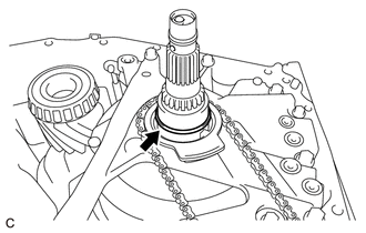
Apply a small amount of MP grease to the entire circumference of the clutch drum oil seal ring installation groove portion.
- HINT:
-
By applying MP grease, the wobble within the clutch drum oil seal ring installation groove will be eliminated, preventing damage to the clutch drum oil seal ring at the time of torque converter assembly installation.
Coat a new clutch drum oil seal ring with Toyota Genuine ATF WS and install it to the front oil pump assembly.
- NOTICE:
-
While making the spread of the opening of the clutch drum oil seal ring as small as possible, install it to the front oil pump assembly. If the ring opening is spread, briefly hold it closed with your fingers to return it to its original condition.
85.INSTALL DIFFERENTIAL CASE ASSEMBLY
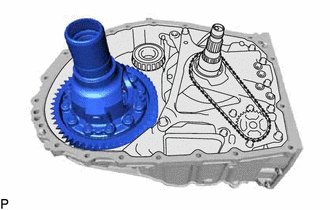
Install the differential case assembly to the automatic transaxle case sub-assembly.
35847C
86.INSTALL TRANSMISSION LUBE APPLY TUBE
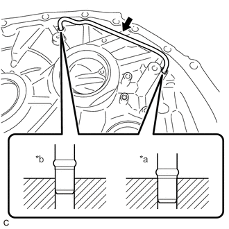
| *a | Correct |
| *b | Incorrect |
Install the transmission lube apply tube to the transaxle housing.
- NOTICE:
-
Insert the transmission lube apply tube until its spool portion is contacting the transaxle housing.
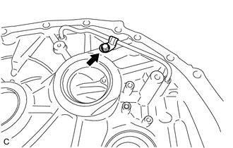
Install the clamp to the transaxle housing with the bolt.
- Torque:
- 5.4 N*m (55 kgf*cm, 48 in.*lbf)
35882C
87.INSTALL DIFFERENTIAL GEAR LUBE APPLY TUBE
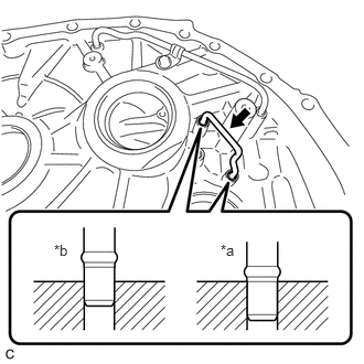
| *a | Correct |
| *b | Incorrect |
Install the differential gear lube apply tube to the transaxle housing.
- NOTICE:
-
Insert the differential gear lube apply tube until its spool portion is contacting the transaxle housing.
35394
88.INSTALL TRANSMISSION OIL CLEANER MAGNET
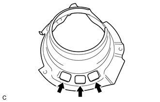
Install the 3 transmission oil cleaner magnets to the transaxle housing oil separator.
35174
89.INSTALL TRANSAXLE HOUSING OIL SEPARATOR
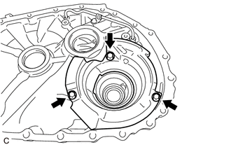
Install the transaxle housing oil separator to the transaxle housing with the 3 bolts.
- Torque:
- 5.4 N*m (55 kgf*cm, 48 in.*lbf)
35111C
90.INSTALL TRANSAXLE HOUSING
- NOTICE:
-
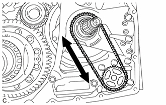
-
When installing the transaxle housing, check that the transmission drive chain rotates smoothly.
Peel off the old seal packing from the transaxle housing and automatic transaxle case sub-assembly installation surface, and clean it.
- NOTICE:
-
Do not damage the installation surface.
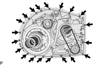
Clean the 20 bolts and bolt holes in the automatic transaxle case sub-assembly.
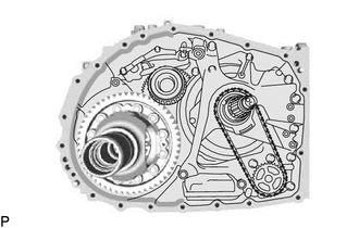

|
Area to be cleaned |
Clean the inner chamfer of the automatic transaxle case sub-assembly shown in the illustration.
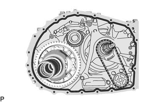
Apply seal packing to the automatic transaxle case sub-assembly as shown in the illustration.
- Seal Packing:
Toyota Genuine Seal Packing 1281, Three Bond 1281 or equivalent
- Standard Seal Diameter:
1.8 mm (0.0709 in.)
- NOTICE:
-
After applying seal packing, install the transaxle housing within 3 minutes and tighten the bolts within 20 minutes of applying the seal packing.
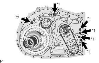
| *1 | Transaxle Case Gasket |
| *2 | O-ring |
Coat 5 new transaxle case gaskets with Toyota Genuine ATF WS and install them to the front oil pump assembly.
Coat a new O-ring with Toyota Genuine ATF WS and install it to the automatic transaxle case sub-assembly.
Install the transaxle housing to the automatic transaxle case sub-assembly with the 9 bolts (A) and 11 bolts (B).
- Torque:
- 29.4 N*m (300 kgf*cm, 22 ft.*lbf)
- Bolt Length:
Bolt (A) Bolt (B) 40 mm (1.57 in.) 35 mm (1.38 in.)
41110G
91.INSTALL DIFFERENTIAL SIDE OIL SEAL
92.INSPECT INPUT SHAFT END PLAY
89413S
93.INSTALL TRANSMISSION REVOLUTION SENSOR (NC)
89413N
94.INSTALL TRANSMISSION REVOLUTION SENSOR (NT)
35410
95.INSTALL TRANSMISSION VALVE BODY ASSEMBLY (w/ Stop And Start System)
35410
96.INSTALL TRANSMISSION VALVE BODY ASSEMBLY (w/o Stop And Start System)
82125J
97.INSTALL TRANSMISSION WIRE (w/ Stop And Start System)
82125J
98.INSTALL TRANSMISSION WIRE (w/o Stop And Start System)
35151F
99.INSTALL TRANSMISSION CASE SIDE COVER
35104B
100.INSTALL NO. 1 BREATHER PLUG (ATM)
Coat the O-ring portion of the No. 1 breather plug (ATM) with Toyota Genuine ATF WS.
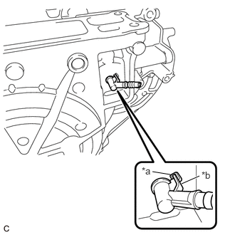
| *a | Indented Portion |
| *b | Detent |
Engage each claw to install a new No. 1 breather plug (ATM) to the automatic transaxle case sub-assembly.
- NOTICE:
-
Securely push in the No. 1 breather plug (ATM) until the No. 1 breather plug (ATM) is engaged.
- HINT:
-
Install the No. 1 breather plug (ATM) with its detent aligned with the indented portion of the automatic transaxle case sub-assembly.
32905
101.INSTALL NO. 1 OIL COOLER OUTLET TUBE SUB-ASSEMBLY
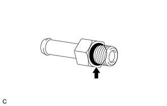
Coat a new O-ring with Toyota Genuine ATF WS and install it to the No. 1 oil cooler outlet tube sub-assembly.
- NOTICE:
-
Ensure that the O-ring is not twisted.
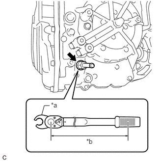
| *a | Union Nut Wrench |
| *b | Torque Wrench Fulcrum Length |
Using a 19 mm union nut wrench, install the No. 1 oil cooler outlet tube sub-assembly to the automatic transaxle case sub-assembly.
- Torque:
- Specified Tightening Torque : 31.1 N*m (317 kgf*cm, 23 ft.*lbf)
- HINT:
- ·
Calculate the torque wrench reading when changing the fulcrum length of the torque wrench.
Click hereGeneral>INTRODUCTION>REPAIR INSTRUCTION>PRECAUTION
·When using a union nut wrench (fulcrum length of 30 mm (1.18 in.)) + torque wrench (fulcrum length of 180 mm (7.09 in.)):
26.7 N*m (272 kgf*cm, 20 ft.*lbf)
32901C
102.INSTALL OIL COOLER UNION SUB-ASSEMBLY
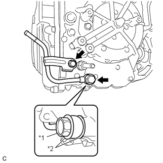
| *1 | Oil Cooler Union Bolt |
| *2 | Gasket |
Pass the oil cooler union sub-assembly through 2 new gaskets and temporarily install it to the automatic transaxle case sub-assembly with the oil cooler union bolt.
Temporarily install the oil cooler union sub-assembly bracket portion to the automatic transaxle case sub-assembly with the bolt.
Tighten the oil cooler union bolt.
- Torque:
- 22.6 N*m (230 kgf*cm, 17 ft.*lbf)
Tighten the bolt.
- Torque:
- 12 N*m (122 kgf*cm, 9 ft.*lbf)
35125C
103.INSTALL NO. 1 TRANSMISSION OIL FILLER TUBE
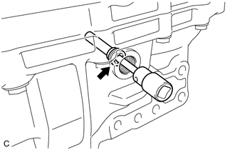
Using a 6 mm socket hexagon wrench, install the No. 1 transmission oil filler tube to the transaxle housing.
- Torque:
- 1.7 N*m (17 kgf*cm, 15 in.*lbf)
104.INSTALL OVERFLOW PLUG
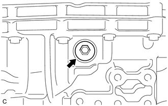
Using a 10 mm socket hexagon wrench, install the overflow plug and a new gasket to the transaxle housing.
- Torque:
- 50 N*m (510 kgf*cm, 37 ft.*lbf)
- NOTICE:
-
To prevent the gasket from being deformed when tightening, coat the gasket with Toyota Genuine ATF WS.
105.INSTALL REFILL PLUG
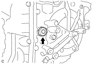
Install the refill plug and a new gasket to the automatic transaxle case sub-assembly.
- Torque:
- 49 N*m (500 kgf*cm, 36 ft.*lbf)
- NOTICE:
-
To prevent the gasket from being deformed when tightening, coat the gasket with Toyota Genuine ATF WS.
84540
106.INSTALL PARK/NEUTRAL POSITION SWITCH ASSEMBLY
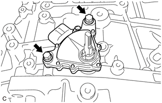
Temporarily install the park/neutral position switch assembly to the automatic transaxle case sub-assembly with the 2 bolts.
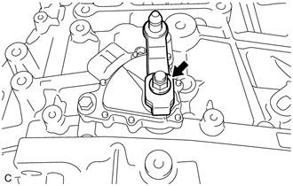
Temporarily install the transmission control shaft lever to the manual valve lever shaft sub-assembly.
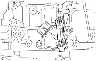
| *a | P |
| *b | N |
Turn the transmission control shaft lever clockwise until it stops, then turn it counterclockwise 2 notches.
Remove the transmission control shaft lever from the manual valve lever shaft sub-assembly.
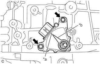
| *a | Neutral Basic Line |
| *b | Protrusion |
Align the protrusion with the neutral basic line.
Hold the park/neutral position switch assembly in that position and tighten the 2 bolts.
- Torque:
- 5.4 N*m (55 kgf*cm, 48 in.*lbf)
35572A
107.INSTALL TRANSMISSION CONTROL SHAFT LEVER
Install the transmission control shaft lever to the manual valve lever shaft sub-assembly with the washer and nut.
- NOTICE:
-
Be careful of the assembly direction of the transmission control shaft lever.
- Torque:
- 12.7 N*m (130 kgf*cm, 9 ft.*lbf)