SLIDING ROOF / CONVERTIBLE SLIDING ROOF HOUSING(for Panoramic Moon Roof) INSTALLATION
CAUTION / NOTICE / HINT
- HINT:
-
Refer to Step 1 for the sliding roof weatherstrip attachment procedure.
PROCEDURE

 1.INSTALL SLIDING ROOF WEATHER STRIP
- HINT:
-
Perform this procedure only when replacement of the sliding roof weatherstrip is necessary.
Use a cloth, etc. to remove the double-sided tape remaining on the sliding roof housing sub-assembly.
- NOTICE:
- ·
Attaching the sliding roof weatherstrip with some double-sided tape remaining may cause poor adhesion.
·Removing with a screwdriver, etc. may cause damage or poor adhesion.
Clean the attachment location of the double-sided tape on the sliding roof housing sub-assembly using non-residue solvent.
Using a brush or sponge, coat the body primer to the area on the sliding roof housing sub-assembly shown in the illustration.
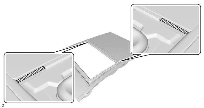

|
Body Primer Application Area | - | - |
Connect the new sliding roof weatherstrip to the sliding roof glass to the sliding roof housing sub-assembly.
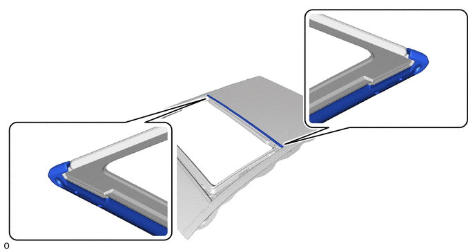
- HINT:
-
Engage both ends of the sliding roof weatherstrip to the sliding roof housing sub-assembly as shown in the illustration.
Remove the peeling paper from the sliding roof weatherstrip.
- HINT:
-
After removing the peeling paper, keep the exposed adhesive free from foreign matter.
Press the double-sided tape on the sliding roof weatherstrip firmly to install.
- HINT:
- ·
Press the sliding roof weatherstrip with force of 50 N (5 kgf, 11.2 lbf).
·Leave the sliding roof weatherstrip without touching it for approximately 30 minutes after installation.
63203F
2.INSTALL SLIDING ROOF HOUSING SUB-ASSEMBLY
Pass a string under the windshield outside moulding as shown in the illustration.
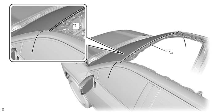
| *1 | Windshield Outside Moulding | - | - |
| *a | String | - | - |
Attach the guide in the order shown in the illustration.
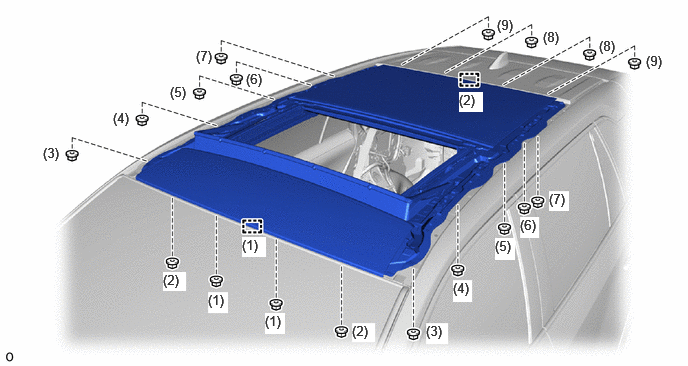
Temporarily install the sliding roof housing sub-assembly with the 18 nuts.
Tighten the 18 nuts to install the sliding roof housing sub-assembly.
- HINT:
-
Tighten the nuts in the order shown in the illustration.
- Torque:
- 5.5 N*m (56 kgf*cm, 49 in.*lbf)
- NOTICE:
-

-
If the removed nut is the same shape as that shown in the illustration, replace it the supplied replacement part.
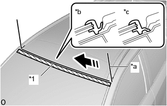
| *1 | Windshield Outside Moulding |
| *a | String |
| *b | Correct |
| *c | Incorrect |

|
String Pulling Direction |
Apply soapy water to the windshield outside moulding.
Slowly pull out the string to install the windshield outside moulding to the correct position.
63246D
3.INSTALL REAR SLIDING ROOF HOUSING MOUNTING BRACKET LH
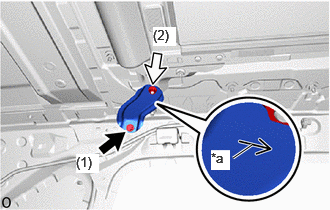
| *a | Arrow Mark (Front) |

|
Bolt |

|
Nut |
Install the rear sliding roof housing mounting bracket LH with the bolt and nut as shown in the illustration.
- Torque:
- Bolt : 8.0 N*m (82 kgf*cm, 71 in.*lbf)
- Nut : 5.5 N*m (56 kgf*cm, 49 in.*lbf)
- NOTICE:
-
-
If the removed nut is the same shape as that shown in the illustration, replace it the supplied replacement part.
63245D
4.INSTALL REAR SLIDING ROOF HOUSING MOUNTING BRACKET RH
- HINT:
-
Use the same procedure as for the LH side.
63244C
5.INSTALL CENTER SLIDING ROOF HOUSING MOUNTING BRACKET LH
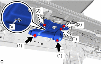
| *a | Arrow Mark (Front) |
|
|
Bolt |
|
|
Nut |
Install the center sliding roof housing mounting bracket LH with the 2 bolts and 2 nuts as shown in the illustration.
- Torque:
- Bolt : 8.0 N*m (82 kgf*cm, 71 in.*lbf)
- Nut : 5.5 N*m (56 kgf*cm, 49 in.*lbf)
- NOTICE:
-
-
If the removed nut is the same shape as that shown in the illustration, replace it the supplied replacement part.
63243C
6.INSTALL CENTER SLIDING ROOF HOUSING MOUNTING BRACKET RH
- HINT:
-
Use the same procedure as for the LH side.
63242A
7.INSTALL FRONT SLIDING ROOF HOUSING MOUNTING BRACKET LH
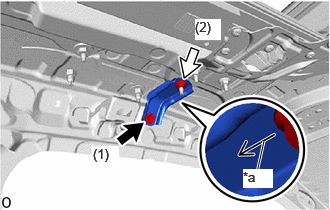
| *a | Arrow Mark (Outside) |
|
|
Bolt |
|
|
Nut |
Install the front sliding roof housing mounting bracket LH with the bolt and nut as shown in the illustration.
- Torque:
- Bolt : 8.0 N*m (82 kgf*cm, 71 in.*lbf)
- Nut : 5.5 N*m (56 kgf*cm, 49 in.*lbf)
- NOTICE:
-
-
If the removed nut is the same shape as that shown in the illustration, replace it the supplied replacement part.
63241A
8.INSTALL FRONT SLIDING ROOF HOUSING MOUNTING BRACKET RH
- HINT:
-
Use the same procedure as for the LH side.
63218M
9.INSTALL SLIDING ROOF SIDE GARNISH LH
Clean the body panel.
Remove the double-sided tape from the body panel.
Clean off any tape adhesive residue with cleaner.
Using a heat light, heat the body panel and sliding roof side garnish LH.
- CAUTION:
-
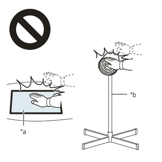 2.365,2 2.698,2 false 0.5,2.333 0.5,2.667 true 0.427,2.708 0.74,2.865 0.313,0.156 10 false *a 2.76,1.927 3.073,2.083 0.313,0.156 10 false *b
*a Heated Part *b Heat Light
- ·
Do not touch the heat light and heated parts, touching the heat light may result in burns.
·Touching heated parts for a long time may result in burns.
| Item | Temperature |
|---|---|
| Body Panel | 40 to 60°C (104 to 140°F) |
| Sliding Roof Side Garnish LH | 20 to 30 °C (68 to 86 °F) |
- NOTICE:
-
Do not heat the sliding roof side garnish LH excessively.
Coat the installation area of the body panel with primer.
Remove the release paper from a new sliding roof side garnish LH.
- HINT:
-
After removing the release paper, keep the exposed adhesive free from foreign matter.
Attach the clip to install the sliding roof side garnish LH as shown in the illustration.
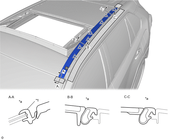
| *1 | Windshield Outside Moulding | - | - |
| *a | Correct | - | - |
|
|
Protective Tape | 
|
Double-sided Tape |
63217K
10.INSTALL SLIDING ROOF SIDE GARNISH RH
- HINT:
-
Use the same procedure described for the LH side.
62180A
11.INSTALL CURTAIN SHIELD AIRBAG ASSEMBLY LH
for Rollover Type:
Click hereVehicle Interior>SUPPLEMENTAL RESTRAINT SYSTEMS>CURTAIN SHIELD AIRBAG ASSEMBLY>INSTALLATION
except Rollover Type:
Click hereVehicle Interior>SUPPLEMENTAL RESTRAINT SYSTEMS>CURTAIN SHIELD AIRBAG ASSEMBLY>INSTALLATION
62170A
12.INSTALL CURTAIN SHIELD AIRBAG ASSEMBLY RH
- HINT:
-
Use the same procedure described for the LH side.
13.INSTALL ROOF RACK ASSEMBLY LH
Click hereVehicle Exterior>EXTERIOR PANELS / TRIM>ROOF RACK>INSTALLATION
- HINT:
-
Use the same procedure for the RH side.
63201P
14.INSTALL SLIDING ROOF GLASS SUB-ASSEMBLY
- NOTICE:
- ·
Carrying the sliding roof glass sub-assembly from the vehicle must be performed by multiple people.
·Be careful not to damage the sliding roof glass sub-assembly, body exterior or interior parts.
Using a T25 "TORX" socket wrench, temporarily install the sliding roof glass sub-assembly with the 6 "TORX" screws.
Perform a level check.
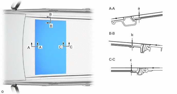
Check the difference in level of the sliding roof glass sub-assembly when the sliding roof glass sub-assembly is fully closed.
| Area | Measurement | Area | Measurement |
|---|---|---|---|
| a | 0 + 2.0 mm (0 + 0.0787 in.)
0 - 1.0 mm (0 + 0.0394 in.) |
b | 0 + 2.2 mm (0 + 0.0866 in.)
0 - 2.2 mm (0 - 0.0866 in.) |
| c | 0 + 2.4 mm (0 + 0.0945 in.)
0 - 1.0 mm (0 + 0.0394 in.) |
- | - |
Perform a gap check.
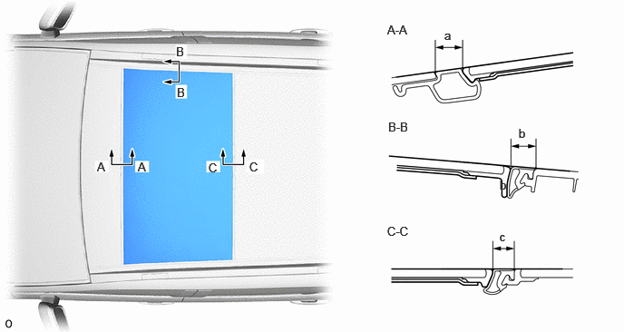
Check the gap between the sliding roof glass sub-assembly and sliding roof housing assembly.
| Area | Measurement | Area | Measurement |
|---|---|---|---|
| a | 10.7 to 12.7 (0.421 to 0.50 in.) | b | 7.7 to 12.1 (0.303 to 0.476 in.) |
| c | 7.9 to 11.1 mm (0.311 to 0.437 in.) | - | - |
After adjusting the sliding roof glass sub-assembly, using a T25 "TORX" socket wrench, tighten the 6 "TORX" screws.
- Torque:
- 5.0 N*m (51 kgf*cm, 44 in.*lbf)
15. CHECK FOR WATER LEAK
After adjusting the sliding roof glass sub-assembly, check for water leakage into the vehicle interior.
If there are any leaks, readjust the sliding roof glass sub-assembly.
63218E
16.INSTALL FRONT SLIDING ROOF GARNISH LH (for Front Outer Side)
Attach the guide to install the front sliding roof side garnish LH.
63217E
17.INSTALL FRONT SLIDING ROOF GARNISH RH (for Front Outer Side)
- HINT:
-
Use the same procedure described for the LH side.
63218R
18.INSTALL SLIDING ROOF SIDE GARNISH LH (for Rear Side)
Attach the guide to install the sliding roof side garnish LH.
63217R
19.INSTALL SLIDING ROOF SIDE GARNISH RH (for Rear Side)
- HINT:
-
Use the same procedure described for the LH side.
63218M
20.INSTALL SLIDING ROOF SIDE GARNISH LH (for Front Inner Side)
Attach the guide to install the sliding roof side garnish LH.
63217K
21.INSTALL SLIDING ROOF SIDE GARNISH RH (for Front Inner Side)
- HINT:
-
Use the same procedure described for the LH side.
22.CONNECT CABLE TO NEGATIVE AUXILIARY BATTERY TERMINAL
for A25A-FXS:
Click hereGeneral>MAINTENANCE>A25A-FXS AUXILIARY BATTERY>INSTALLATION
for A25A-FKS:
for M20A-FKS:
Click hereGeneral>MAINTENANCE>M20A-FKS BATTERY>INSTALLATION
- NOTICE:
-
When disconnecting the cable, some systems need to be initialized after the cable is reconnected.
-
Click hereGeneral>INTRODUCTION>REPAIR INSTRUCTION>INITIALIZATION
23. PERFORM DIAGNOSTIC SYSTEM CHECK
24.CHECK SRS WARNING LIGHT
25.PERFORM SYSTEM INITIALIZATION AND CALIBRATION
26.INITIALIZE ROOF SUNSHADE SYSTEM
27.INITIALIZE PANORAMIC MOON ROOF SYSTEM
Click hereVehicle Exterior>SLIDING ROOF / CONVERTIBLE>PANORAMIC MOON ROOF SYSTEM>INITIALIZATION
- NOTICE:
-
Before initializing the panoramic moon roof system, first initialize the roof sunshade system.
28.CHECK ROOF SUNSHADE SYSTEM
29.CHECK PANORAMIC MOON ROOF SYSTEM