M20A-FKS COOLING THERMOSTAT REMOVAL
CAUTION / NOTICE / HINT
The necessary procedures (adjustment, calibration, initialization, or registration) that must be performed after parts are removed, installed, or replaced during the water inlet with thermostat sub-assembly removal/installation are shown below.
| Replaced Part or Performed Procedure | Necessary Procedure | Effect/Inoperative Function when Necessary Procedure not Performed | Link |
|---|---|---|---|
|
*: When performing learning using the GTS. Click here |
|||
| Battery terminal is disconnected/reconnected | Drive the vehicle until stop and start control is permitted (approximately 5 to 60 minutes) | Stop and start system | ( ) |
| Perform steering sensor zero point calibration | Lane control system | ()
|
|
| Parking support brake system* | |||
| Pre-collision system | |||
| Memorize steering angle neutral point | Parking assist monitor system | ()
|
|
| Panoramic view monitor system (for Gasoline Model) | ()
|
||
| Reset back door close position | Power back door function | ()
|
|
| Power back door initialization | Power door lock control system | ()
|
|
·
Replacement of throttle body with motor assembly ·
Replacement of EGR valve assembly ·
Gas leaks from exhaust system |
Inspection after repair | ·
Poor idle, etc. ·
Engine start function, etc. |
()
|
- NOTICE:
- ·
After the ignition switch is turned off, the navigation system requires approximately a minute to record various types of memory and settings. As a result, after turning the ignition switch off, wait a minute or more before disconnecting the cable from the negative (-) battery terminal.
·This procedure includes the removal of small-head bolts. Refer to Small-Head Bolts of Basic Repair Hint to identify the small-head bolts.
Click hereGeneral>INTRODUCTION>REPAIR INSTRUCTION>PRECAUTION
PROCEDURE

 1.DRAIN ENGINE COOLANT
17111
2.REMOVE INTAKE MANIFOLD
27020
3.REMOVE GENERATOR ASSEMBLY
for 100 A, 130 A Type:
Click herePower Source / Network>M20A-FKS (BATTERY / CHARGING)>GENERATOR(for 100 A, 130 A Type)>REMOVAL
for 150 A Type:
Click herePower Source / Network>M20A-FKS (BATTERY / CHARGING)>GENERATOR(for 150 A Type)>REMOVAL
16572D
4.DISCONNECT NO. 2 RADIATOR HOSE
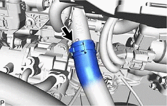
Slide the clip and disconnect the No. 2 radiator hose from the water inlet with thermostat sub-assembly.
16031
5.REMOVE WATER INLET WITH THERMOSTAT SUB-ASSEMBLY
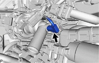
Disconnect the water inlet with thermostat sub-assembly connector.
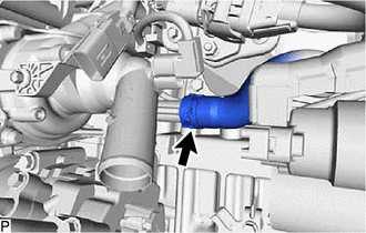
Slide the clip and disconnect the No. 7 water by-pass hose from the water inlet with thermostat sub-assembly.
- NOTICE:
- ·
Do not apply force to the water inlet with thermostat sub-assembly when disconnecting the No. 7 water by-pass hose.
·Do not damage the water inlet with thermostat sub-assembly.
- HINT:
-
When disconnecting the No. 7 water by-pass hose, slide the clip, rotate the hose and pull it straight off the pipe.
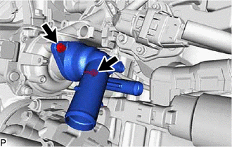
Using an 8 mm socket wrench, remove the 2 bolts and water inlet with thermostat sub-assembly.
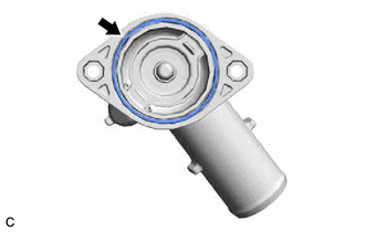
Remove the gasket from the water inlet with thermostat sub-assembly.