EG62F MANUAL TRANSMISSION / TRANSAXLE MANUAL TRANSAXLE ASSEMBLY INSTALLATION
CAUTION / NOTICE / HINT
- CAUTION:
-
The engine assembly with transaxle is very heavy. Be sure to follow the procedure described in the repair manual, or the engine lifter may suddenly drop or the engine assembly with transaxle may fall off the engine lifter.
- NOTICE:
-
When the manual transaxle assembly is removed, be sure to use a new clutch release with bearing cylinder assembly and new installation bolts. Removal of the manual transaxle assembly allows the compressed clutch release with bearing cylinder assembly to return to its original position. Dust from the moving section may damage the seal of the clutch release with bearing cylinder assembly, possibly causing clutch fluid leaks.
PROCEDURE

 36100A
1.INSTALL TRANSFER AND TRANSAXLE SETTING STUD BOLT
- HINT:
-
It is not necessary to remove the transfer and transaxle setting stud bolts unless they are being replaced.
for Transfer Side:
Click hereDrivetrain>GF1A (TRANSFER / 4WD / AWD)>TRANSFER ASSEMBLY>REASSEMBLY
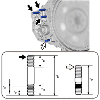
| *a | 22 mm (0.866 in.) |
| *b | 69 mm (2.72 in.) |
| *c | 5.0 to 7.5 mm (0.200 to 0.300 in.) |
| *d | 13 mm (0.512 in.) |
| *e | 47 mm (1.85 in.) |

|
Sealant |

|
Adhesive 1324 |

|
Transfer and Transaxle Setting Stud Bolt A |

|
Transfer and Transaxle Setting Stud Bolt B |
for Manual Transaxle Assembly Side:
- NOTICE:
-
There are 2 types of transfer assembly installation conditions, a type using only nuts and a type using nuts and bolts.
-
Install stud bolts according to the transfer assembly installation condition of the vehicle.
-
Click hereDrivetrain>GF1A (TRANSFER / 4WD / AWD)>TRANSFER ASSEMBLY>INSTALLATION
Clean the transfer and transaxle setting stud bolt holes.
for Transfer and Transaxle Setting Stud Bolt A:
Apply adhesive 1324 to 2 or 3 threads on one half of 3 new transfer and transaxle setting stud bolts A as shown in the illustration.
- Adhesive:
Toyota Genuine Adhesive 1324, Three Bond 1324 or equivalent
- NOTICE:
- ·
Do not apply adhesive 1324 to the ends of the transfer and transaxle setting stud bolts A.
·Install the transfer and transaxle setting stud bolts A immediately after applying adhesive 1324 to prevent the adherence of foreign matter.
·Install the transfer and transaxle setting stud bolts A so that the side that has adhesive 1324 is facing the manual transaxle assembly.
Install the 3 transfer and transaxle setting stud bolts A to the manual transaxle assembly positions shown in the illustration.
- Torque:
39.2 N*m (400 kgf*cm, 29 ft.*lbf)
for Transfer and Transaxle Setting Stud Bolt B:
Install a new transfer and transaxle setting stud bolt B to the manual transaxle assembly positions shown in the illustration.
- Torque:
39.2 N*m (400 kgf*cm, 29 ft.*lbf)
- NOTICE:
-
Install the transfer and transaxle setting stud bolt B so that the side that has sealant is facing the manual transaxle assembly.
36100
2.INSTALL TRANSFER ASSEMBLY
35150D
3.INSTALL TRANSMISSION CASE PLUG ASSEMBLY
Coat the O-ring of a new transmission case plug assembly with gear oil.
Install the transmission case plug assembly to the manual transaxle assembly.
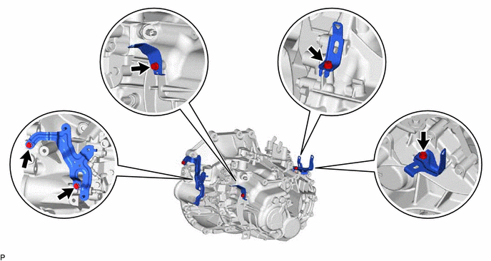
4.INSTALL WIRE HARNESS CLAMP BRACKET
Install the 4 wire harness clamp brackets with the 5 bolts.
- Torque:
- 10 N*m (102 kgf*cm, 7 ft.*lbf)
335A0
5.INSTALL CONTROL CABLE BRACKET ASSEMBLY
Install the control cable bracket assembly to the manual transaxle assembly with the 3 bolts.
- Torque:
- 17 N*m (173 kgf*cm, 13 ft.*lbf)
31485
6.INSTALL CLUTCH FLEXIBLE HOSE BRACKET
Install the clutch flexible hose bracket to the manual transaxle assembly with the bolt.
- Torque:
- 11 N*m (112 kgf*cm, 8 ft.*lbf)
31482F
7.INSTALL CLUTCH RELEASE CYLINDER WITH BEARING ASSEMBLY TO BLEEDER TUBE
31407B
8.INSTALL CLUTCH RELEASE BLEEDER SUB-ASSEMBLY
31400
9.INSTALL CLUTCH RELEASE CYLINDER WITH BEARING ASSEMBLY
31488F
10.INSTALL BLEEDER TO FLEXIBLE HOSE TUBE
30300
11.INSTALL MANUAL TRANSAXLE ASSEMBLY
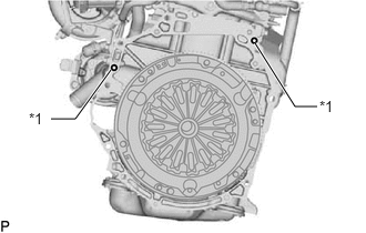
| *1 | Knock Pin |
Check that the 2 knock pins are installed on the engine assembly before installing the manual transaxle assembly.
Align the input shaft with the clutch disc and install the manual transaxle assembly to the engine assembly.
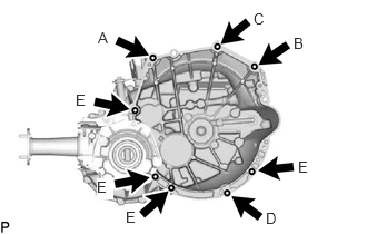
Temporarily install the bolt A.
- HINT:
-
Bolt A: Install from the manual transaxle assembly side.
Install the bolt B.
- Torque:
- 64 N*m (653 kgf*cm, 47 ft.*lbf)
- HINT:
-
Bolt B: Install from the manual transaxle assembly side.
Install the bolt C, then fully tighten the bolt A.
- Torque:
- for bolt C : 64 N*m (653 kgf*cm, 47 ft.*lbf)
- for bolt A : 46 N*m (469 kgf*cm, 34 ft.*lbf)
- HINT:
-
Bolt C: Install from the manual transaxle assembly side.
Install the bolt D.
- Torque:
- 25 N*m (255 kgf*cm, 18 ft.*lbf)
- HINT:
-
Bolt D: Install from the manual transaxle assembly side.
Install the 4 bolts E.
- Torque:
- 46 N*m (469 kgf*cm, 34 ft.*lbf)
- NOTICE:
- ·
Make sure that the wire harness or similar items are not pinched between the contact surfaces.
·Do not forcibly pry on the engine assembly when installing it to the manual transaxle assembly.
·Do not apply excessive force to the manual transaxle assembly as this will break the input shaft.
·Make sure that the knock pins fit securely into the holes when installing the manual transaxle assembly to the engine assembly.
·Make sure that the contact surfaces of the engine assembly and manual transaxle assembly are flat against each other before tightening the bolts.
- HINT:
-
Bolt E: Install from the engine assembly side.
28100
12.INSTALL STARTER ASSEMBLY
for 1.2 kW Type:
Click hereEngine / Hybrid System>M20A-FKS (STARTING)>STARTER (for 1.2 kW Type)>INSTALLATION
w/ Stop and Start System:
11363A
13.INSTALL FLYWHEEL HOUSING SIDE COVER
12303
14.INSTALL REAR ENGINE MOUNTING BRACKET SUB-ASSEMBLY
Install the rear No. 2 engine mounting bracket to the rear engine mounting bracket with the 2 bolts.
- Torque:
- 42 N*m (428 kgf*cm, 31 ft.*lbf)
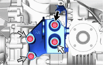
|
|
Bolt A |
|
|
Bolt B |

|
Bolt C |
Install the rear engine mounting bracket sub-assembly to the manual transaxle assembly with the 4 bolts.
- Torque:
- 42 N*m (428 kgf*cm, 31 ft.*lbf)
- HINT:
-
Tightening order: Temporarily install bolt (A) → Tighten bolt (B) → Tighten bolt (A) → Tighten bolt (C)
12371A
15.INSTALL REAR ENGINE MOUNTING INSULATOR
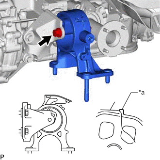
| *a | Rubber Protrusion |
Install the rear engine mounting insulator to the rear engine mounting bracket sub-assembly with the bolt and nut.
- Torque:
- 72 N*m (734 kgf*cm, 53 ft.*lbf)
- NOTICE:
-
Align the rubber protrusion of the rear engine mounting insulator with the shape of the rear engine mounting bracket sub-assembly.
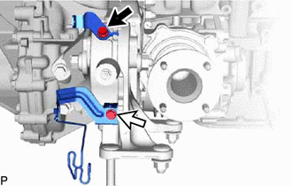
|
|
Bolt A |
|
|
Bolt B |
Install the 2 wire harness clamp brackets to the rear engine mounting insulator with the 2 bolts.
- Torque:
- for bolt A : 10 N*m (102 kgf*cm, 7 ft.*lbf)
- for bolt B : 13 N*m (133 kgf*cm, 10 ft.*lbf)
12311A
16.INSTALL TRANSVERSE ENGINE ENGINE MOUNTING BRACKET
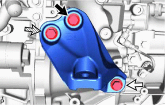
|
|
Bolt A |
|
|
Bolt B |
|
|
Bolt C |
Install the transverse engine engine mounting bracket to the manual transaxle assembly with the 3 bolts.
- Torque:
- 42 N*m (428 kgf*cm, 31 ft.*lbf)
- HINT:
-
Tightening order: Temporarily install bolt (A) → Tighten bolt (B) → Tighten bolt (C) → Tighten bolt (A)
12361
17.INSTALL FRONT ENGINE MOUNTING INSULATOR
Install the front engine mounting insulator to the transverse engine engine mounting bracket with the bolt.
- Torque:
- 72 N*m (734 kgf*cm, 53 ft.*lbf)
12372A
18.INSTALL TRANSVERSE ENGINE ENGINE MOUNTING INSULATOR
Install the transverse engine engine mounting insulator to the manual transaxle assembly with the 5 bolts.
- Torque:
- 42 N*m (428 kgf*cm, 31 ft.*lbf)
37117
19.INSTALL PROPELLER SHAFT HEAT INSULATOR
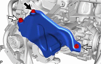
|
|
Bolt A |
|
|
Bolt B |
|
|
Bolt C |
Install the propeller shaft heat insulator to the manual transaxle assembly with the 3 bolts.
- Torque:
- 18 N*m (184 kgf*cm, 13 ft.*lbf)
- HINT:
-
Tightening order: Temporarily install bolt (A) → Temporarily install bolt (B) → Tighten bolt (C) → Tighten bolt (B) → Tighten bolt (A)
20.CONNECT WIRE HARNESS
Connect the wire harness to the manual transaxle assembly.
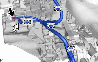
|
|
Bolt |
|
|
Back-up Light Switch Assembly Connector |
Attach the 4 clamps.
Connect the back-up light switch assembly connector and install the bolt.
- Torque:
- 10 N*m (102 kgf*cm, 7 ft.*lbf)
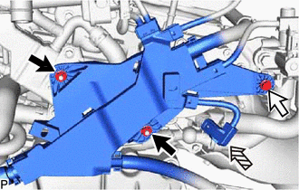
|
|
Nut |
|
|
Bolt |
|
|
Engine Coolant Temperature Sensor Connector |
Connect the engine coolant temperature sensor connector.
Install the 2 nuts and bolt.
- Torque:
- 10 N*m (102 kgf*cm, 7 ft.*lbf)
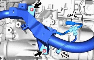
|
|
Nut |
|
|
Neutral Position Switch Connector |
|
|
Transmission Revolution Sensor Connector |
Connect the neutral position switch connector and transmission revolution sensor connector.
Install the 2 nuts.
- Torque:
- 10 N*m (102 kgf*cm, 7 ft.*lbf)
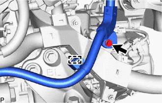
Attach the clamp and install the bolt.
- Torque:
- 10 N*m (102 kgf*cm, 7 ft.*lbf)
51100H
21.INSTALL FRONT FRAME ASSEMBLY
22.CONNECT WIRE HARNESS (for RHD)
23.CONNECT WIRE HARNESS (for LHD)
45319
24.INSTALL STEERING GEAR HEAT INSULATOR (for LHD)
25.REMOVE ENGINE HANGERS
23825
26.INSTALL FUEL DELIVERY GUARD
17141
27.INSTALL EXHAUST MANIFOLD
28.INSTALL ENGINE ASSEMBLY WITH TRANSAXLE