Home › Vehicle Exterior › LIGHTING (EXT) › LIGHTING SYSTEM
RM3620E _59 Vehicle Exterior _077130 LIGHTING (EXT) _0375584 LIGHTING SYSTEM J

LIGHTING (EXT)  LIGHTING SYSTEM  Back-up Light Circuit  


DESCRIPTION

The hybrid vehicle control ECU assembly controls the back-up lights via the BKUP LP relay.

WIRING DIAGRAM
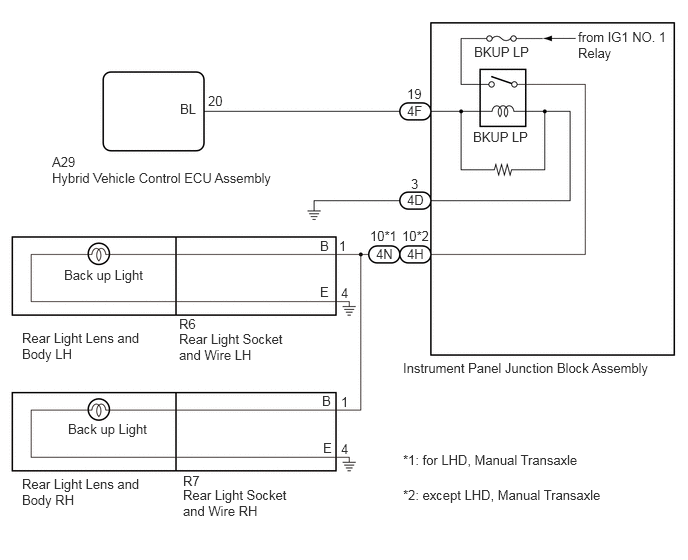
E411297E01
0.542,1.604 1.042,1.833 0.5,0.229 10 false A29 0.542,1.771 3.344,2.167 2.802,0.396 10 false Hybrid Vehicle Control ECU Assembly 1.875,1.052 2.375,1.281 0.5,0.229 10 false BL 2.167,0.969 2.667,1.198 0.5,0.229 10 false 20 4.24,0.896 4.74,1.125 0.5,0.229 10 false 19 6.021,0.302 7.01,0.677 0.99,0.375 10 false from IG1 NO. 1 Relay 4.938,0.458 5.635,0.667 0.698,0.208 10 false BKUP LP 4.198,3.75 6.875,4.042 2.677,0.292 10 false Instrument Panel Junction Block Assembly 1.906,4.927 2.406,5.156 0.5,0.229 10 false R7 0.229,4.958 1.479,5.302 1.25,0.344 10 false Rear Light Lens and Body RH 1.865,3.292 2.365,3.521 0.5,0.229 10 false R6 1.865,3.448 2.99,3.792 1.125,0.344 10 false Rear Light Socket and Wire LH 0.667,2.781 1.635,3.01 0.969,0.229 10 false Back up Light 3.333,2.479 3.833,2.708 0.5,0.229 10 false B 3.333,2.958 3.833,3.188 0.5,0.229 10 false E 4.24,1.073 4.74,1.302 0.5,0.229 10 false 4F 4.24,2 4.74,2.229 0.5,0.229 10 false 4D 4.24,2.563 4.74,2.792 0.5,0.229 10 false 4H 3.854,2.375 4.354,2.604 0.5,0.229 10 false 10*1 4.281,1.833 4.781,2.063 0.5,0.229 10 false 3 3.552,2.969 4.052,3.198 0.5,0.229 10 false 4 3.552,4.594 4.052,4.823 0.5,0.229 10 false 4 4.927,1.344 5.625,1.552 0.698,0.208 10 false BKUP LP 3.531,2.479 4.031,2.708 0.5,0.229 10 false 1 3.552,4.104 4.052,4.333 0.5,0.229 10 false 1 0.708,4.385 1.677,4.615 0.969,0.229 10 false Back up Light 3.365,4.583 3.865,4.813 0.5,0.229 10 false E 3.354,4.094 3.854,4.323 0.5,0.229 10 false B 0.229,3.438 1.479,3.781 1.25,0.344 10 false Rear Light Lens and Body LH 1.906,5.073 3.031,5.417 1.125,0.344 10 false Rear Light Socket and Wire RH 3.917,2.563 4.417,2.792 0.5,0.229 10 false 4N 4.188,2.375 4.688,2.604 0.5,0.229 10 false 10*2 4.198,4.708 6.875,5 2.677,0.292 10 false *1: for LHD, Manual Transaxle 4.198,5.073 6.875,5.365 2.677,0.292 10 false *2: except LHD, Manual Transaxle

CAUTION / NOTICE / HINT

NOTICE:
·

Inspect the fuses for circuits related to this system before performing the following procedure.

·

Before replacing the hybrid vehicle control ECU assembly, refer to Service Bulletin.


PROCEDURE

1.CHECK FOR DTC
a.

Connect the GTS to the DLC3.


b.

Turn the ignition switch to ON.


c.

Turn the GTS on.


d.

Enter the following menus: Powertrain / Hybrid Control / Trouble Codes.


e.

Check for DTCs.

Powertrain > Hybrid Control > Trouble Codes
50001 397

Result:
Result Proceed to
Hybrid control system DTCs are not output A
Hybrid control system DTCs are output B


A

2.CHECK HARNESS AND CONNECTOR (INSTRUMENT PANEL JUNCTION BLOCK ASSEMBLY - BODY GROUND)

B

2.CHECK HARNESS AND CONNECTOR (INSTRUMENT PANEL JUNCTION BLOCK ASSEMBLY - BODY GROUND)
a.

Disconnect the 4D instrument panel junction block assembly connector.


b.

Measure the resistance according to the value(s) in the table below.

Standard Resistance:
Tester Connection Condition Specified Condition
4D-3 - Body ground Always Below 1 Ω


Result:
Proceed to
OK
NG


OK

3.CHECK HARNESS AND CONNECTOR (HYBRID VEHICLE CONTROL ECU ASSEMBLY - INSTRUMENT PANEL JUNCTION BLOCK ASSEMBLY)

NG

REPAIR OR REPLACE HARNESS OR CONNECTOR

3.CHECK HARNESS AND CONNECTOR (HYBRID VEHICLE CONTROL ECU ASSEMBLY - INSTRUMENT PANEL JUNCTION BLOCK ASSEMBLY)
a.

Disconnect the 4F instrument panel junction block assembly connector.


b.

Disconnect the A29 hybrid vehicle control ECU assembly connector.


c.

Measure the resistance according to the value(s) in the table below.

Standard Resistance:
Tester Connection Condition Specified Condition
A29-20 (BL) - 4F-19 Always Below 1 Ω
A29-20 (BL) or 4F-19 - Body ground Always 10 kΩ or higher


Result:
Proceed to
OK
NG


OK

4.CHECK HYBRID VEHICLE CONTROL ECU ASSEMBLY (OUTPUT VOLTAGE)

NG

REPAIR OR REPLACE HARNESS OR CONNECTOR

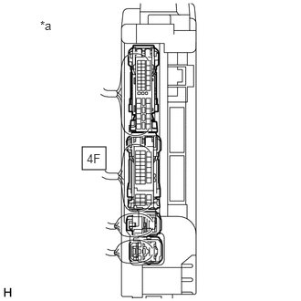
4.CHECK HYBRID VEHICLE CONTROL ECU ASSEMBLY (OUTPUT VOLTAGE)
E356599C25
0.938,1.677 1.208,1.938 0.271,0.26 0.99,1.729 1.302,1.927 0.313,0.198 10 false 4F 0.458,0.208 0.771,0.406 0.313,0.198 10 false *a
*a Component with harness connected
(Instrument Panel Junction Block Assembly)


a.

Measure the voltage according to the value(s) in the table below.

Standard Voltage:
Tester Connection Condition Specified Condition
4F-19 - Body ground Ignition switch ON, shift lever not in R Below 1 V
4F-19 - Body ground Ignition switch on (IG), shift lever in R 11 to 14 V


Result:
Proceed to
OK
NG


OK

5.INSPECT INSTRUMENT PANEL JUNCTION BLOCK ASSEMBLY (OUTPUT VOLTAGE)

NG

REPLACE HYBRID VEHICLE CONTROL ECU ASSEMBLY

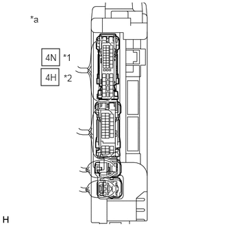
5.INSPECT INSTRUMENT PANEL JUNCTION BLOCK ASSEMBLY (OUTPUT VOLTAGE)
E356599C26
0.635,0.74 0.906,1 0.271,0.26 0.625,1.042 0.896,1.302 0.271,0.26 0.688,0.792 1,0.99 0.313,0.198 10 false 4N 0.458,0.208 0.771,0.406 0.313,0.198 10 false *a 0.688,1.094 1,1.292 0.313,0.198 10 false 4H 0.958,0.792 1.271,0.99 0.313,0.198 10 false *1 0.969,1.104 1.281,1.302 0.313,0.198 10 false *2
*a Component with harness connected
(Instrument Panel Junction Block Assembly)
*1 for LHD, Manual Transaxle
*2 except LHD, Manual Transaxle


a.

Measure the voltage according to the value(s) in the table below.

Standard Voltage:
for LHD, Manual Transaxle:
Tester Connection Condition Specified Condition
4N-10 - Body ground Ignition switch ON, shift lever not in R Below 1 V
4N-10 - Body ground Ignition switch ON, shift lever in R 11 to 14 V

except LHD, Manual Transaxle:
Tester Connection Condition Specified Condition
4H-10 - Body ground Ignition switch ON, shift lever not in R Below 1 V
4H-10 - Body ground Ignition switch ON, shift lever in R 11 to 14 V


Result:
Proceed to
OK
NG


OK

REPAIR OR REPLACE HARNESS OR CONNECTOR

NG