PARKING BRAKE ELECTRIC PARKING BRAKE SYSTEM(w/ Vacuum Brake Booster) Electric Parking Brake System AUTO Function Circuit
DESCRIPTION
The electric parking brake system AUTO function (IG-OFF linked function) is controlled by the skid control ECU (brake actuator assembly) based on whether it receives input voltage or not.
When the ignition switch is turned off, the electric parking brake system AUTO function (IG-OFF linked function) automatically operates to apply the electric parking brake.
The skid control ECU (brake actuator assembly) receives shift position signals from the ECM via CAN communication to control the electric parking brake system AUTO function (IG-OFF linked function).
The electric parking brake system AUTO function (IG-OFF linked function) is automatically disabled when the ignition switch is ON, the brake pedal is depressed and the shift lever is moved out of P. Then, if the shift lever is moved to P, the AUTO function (IG-OFF linked function) automatically operates to apply the electric parking brake.
WIRING DIAGRAM
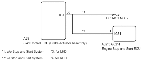
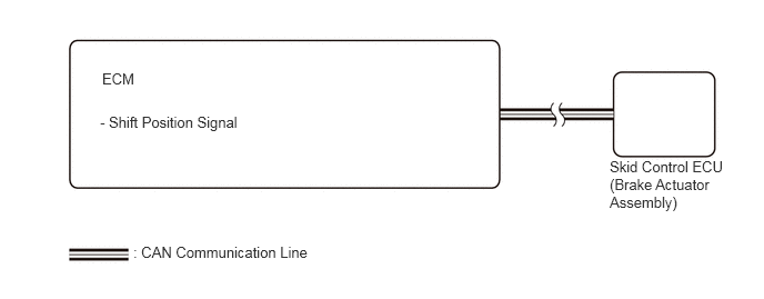
CAUTION / NOTICE / HINT
- NOTICE:
- ·
The AUTO function (IG-OFF linked function) will not automatically operate if the electric parking brake switch assembly (brake warning switch assembly) is moved to the release side when the ignition switch is turned off. (for Manual Transaxle)
·The AUTO function (IG-OFF linked function) will not be automatically disabled when the ignition switch is ON, the brake pedal is depressed and the shift lever is moved out from P if the electric parking brake switch assembly (integration control and panel assembly) is moved to the engage side. The AUTO function (IG-OFF linked function) will not automatically operate to apply the electric parking brake when the shift lever is moved to P if the electric parking brake switch assembly (integration control and panel assembly) is moved to the release side. (except Manual Transaxle)
·The electric parking brake may still operate up to 20 seconds after the ignition switch is turned off. Before disconnecting connectors or fuses, turn the ignition switch off and wait 20 seconds or more.
·Inspect the fuses for circuits related to this system before performing the following procedure. (for Manual Transaxle)
·After replacing the skid control ECU (brake actuator assembly), perform acceleration sensor zero point calibration and store system information memorization.
·When replacing the skid control ECU (brake actuator assembly), operate the electric parking brake switch (brake warning switch assembly)*1 or electric parking brake switch (integration control and panel assembly)*2 as the parking brake indicator light blinks when the ignition switch is first turned to ON.
*1: for Manual Transaxle
*2: except Manual Transaxle
PROCEDURE
Check the vehicle specification.
- Result:
Result Proceed to for Manual Transaxle A except Manual Transaxle B
A
B
Disconnect the A39 skid control ECU (brake actuator assembly) connector.
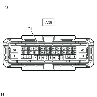
| *a | Front view of wire harness connector
(to Skid Control ECU (Brake Actuator Assembly)) |
Measure the voltage according to the value(s) in the table below.
- Standard Voltage:
Tester Connection Condition Specified Condition A39-36 (IG1) - Body ground IG OFF Below 1 V
- Result:
Proceed to OK NG (w/ Stop and Start System) NG (w/o Stop and Start System)
OK
for LHD: Click hereBrake>BRAKE CONTROL / DYNAMIC CONTROL SYSTEMS>BRAKE ACTUATOR (for LHD with Vacuum Brake Booster)>REMOVAL
for RHD: Click hereBrake>BRAKE CONTROL / DYNAMIC CONTROL SYSTEMS>BRAKE ACTUATOR (for RHD with Vacuum Brake Booster)>REMOVAL
NG (w/ Stop and Start System)
NG (w/o Stop and Start System)
Turn the ignition switch off.
Disconnect the A39 skid control ECU (brake actuator assembly) connector.
Disconnect the A32*1 or G62*2 engine stop and start ECU connector.
*1: for LHD
*2: for RHD
Measure the voltage according to the value(s) in the table below.
| Tester Connection | Condition | Specified Condition |
|---|---|---|
| A39-36 (IG1) - Body ground | IG OFF | Below 1 V |
- Result:
Proceed to OK NG
OK
for A25A-FKS: Click hereEngine / Hybrid System>STOP AND START>STOP AND START SYSTEM (for A25A-FKS)>Backup Boost Converter Circuit
for M20A-FKS: Click hereEngine / Hybrid System>STOP AND START>STOP AND START SYSTEM(for M20A-FKS)>Backup Boost Converter Circuit
NG
Check for DTCs.
- Powertrain > Engine > Trouble Codes
- 50001 372
- Result:
Result Proceed to DTC is not output A DTC is output B
A
for LHD: Click hereBrake>BRAKE CONTROL / DYNAMIC CONTROL SYSTEMS>BRAKE ACTUATOR (for LHD with Vacuum Brake Booster)>REMOVAL
for RHD: Click hereBrake>BRAKE CONTROL / DYNAMIC CONTROL SYSTEMS>BRAKE ACTUATOR (for RHD with Vacuum Brake Booster)>REMOVAL
B
for A25A-FKS (w/ Canister Pump Module): Click hereEngine / Hybrid System>A25A-FKS (ENGINE CONTROL)>SFI SYSTEM (w/ Canister Pump Module)>HOW TO PROCEED WITH TROUBLESHOOTING
for A25A-FKS (w/o Canister Pump Module): Click hereEngine / Hybrid System>A25A-FKS (ENGINE CONTROL)>SFI SYSTEM (w/o Canister Pump Module)>HOW TO PROCEED WITH TROUBLESHOOTING
for M20A-FKS: Click hereEngine / Hybrid System>M20A-FKS (ENGINE CONTROL)>SFI SYSTEM>HOW TO PROCEED WITH TROUBLESHOOTING