A25A-FKS COOLING FLOW SHUTTING VALVE(for ATF) REMOVAL
CAUTION / NOTICE / HINT
The necessary procedures (adjustment, calibration, initialization or registration) that must be performed after parts are removed and installed, or replaced during flow shutting valve (No. 1 water by-pass hose) removal/installation are shown below.
| Replaced Part or Performed Procedure | Necessary Procedure | Effect/Inoperative Function when Necessary Procedure not Performed | Link |
|---|---|---|---|
|
*: When performing learning using the GTS. Click here( |
|||
| Battery terminal is disconnected/reconnected | Drive the vehicle until stop and start control is permitted (approximately 5 to 60 minutes) | Stop and start system | ( ) |
| Perform steering sensor zero point calibration | Lane control system | ()
|
|
| Parking support brake system (for Gasoline model)* | |||
| Pre-collision system | |||
| Memorize steering angle neutral point | Parking assist monitor system | ()
|
|
| Panoramic view monitor system (for Gasoline Model) | ()
|
||
| Reset back door close position | Power back door system (for Gasoline model) | ()
|
|
| Power back door initialization | Power door lock control system | ()
|
|
| Replacement of ECM | Perform Vehicle Identification Number (VIN) or frame number registration | DTC P063051 is output | w/ Canister Pump Module:()
w/o Canister Pump Module:( )
|
| ECU communication ID registration | Engine start function | See Service Bulletin for the registration method. | |
for UB80E:
If transaxle compensation code read from ECM -
Perform reset memory -
Transfer transaxle compensation code -
Perform road test to allow ECM to learn |
·
Large shift shock ·
Deterioration of fuel efficiency |
for Initialization:()
for Registration:( )
|
|
for UB80E:
If transaxle compensation code not read from ECM -
Perform reset memory -
Reset transaxle compensation code -
Perform road test to allow ECM to learn |
|||
for UB80F:
If transaxle compensation code read from ECM -
Perform reset memory -
Transfer transaxle compensation code -
Perform road test to allow ECM to learn |
·
Large shift shock ·
Deterioration of fuel efficiency |
for Initialization:()
for Registration:( )
|
|
for UB80F:
If transaxle compensation code not read from ECM -
Perform reset memory -
Reset transaxle compensation code -
Perform road test to allow ECM to learn |
|||
- NOTICE:
-
After the ignition switch is turned off, the navigation system requires approximately a minute to record various types of memory and settings. As a result, after turning the ignition switch off, wait a minute or more before disconnecting the cable from the negative (-) battery terminal.
PROCEDURE

 28800
1.REMOVE BATTERY
89661
2.REMOVE ECM
74404B
3.REMOVE BATTERY CLAMP SUB-ASSEMBLY
4.REMOVE FRONT WHEEL LH
53895B
5.REMOVE FRONT FENDER FRONT SPLASH SHIELD RH
53896B
6.REMOVE FRONT FENDER FRONT SPLASH SHIELD LH
51441
7.REMOVE NO. 1 ENGINE UNDER COVER
51420
8.REMOVE NO. 2 ENGINE UNDER COVER ASSEMBLY
53737D
9.REMOVE FRONT FENDER APRON SEAL LH
10.DRAIN ENGINE COOLANT
16261G
11.REMOVE FLOW SHUTTING VALVE (NO. 1 WATER BY-PASS HOSE)
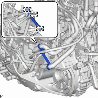
Detach the 3 clamps and remove the transmission breather clamp.
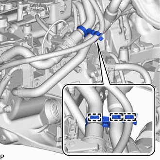
Detach the 3 clamps and remove the hose clamp.
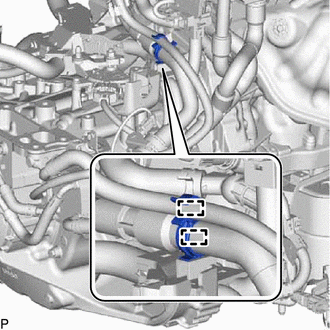
Detach the 2 clamps and disconnect the flow shutting valve (No. 1 water by-pass hose) and transmission breather hose from the hose clamp.
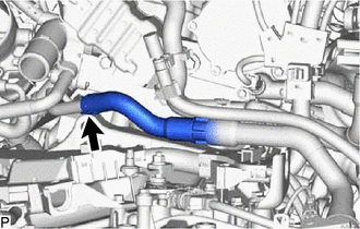
Slide the clip and disconnect the flow shutting valve (No. 1 water by-pass hose) from the water outlet.
- HINT:
-
Use a container to catch any engine coolant which flows out of the flow shutting valve (No. 1 water by-pass hose) and water outlet.
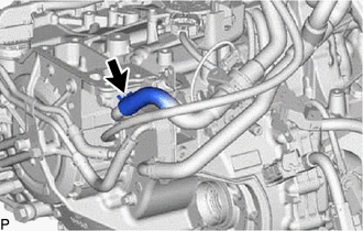
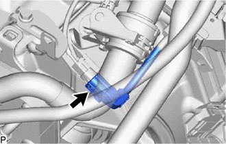
Slide the clip and disconnect the flow shutting valve (No. 1 water by-pass hose) from the transmission oil cooler.
- HINT:
-
Use a container to catch any engine coolant which flows out of the flow shutting valve (No. 1 water by-pass hose) and transmission oil cooler.
Disconnect the flow shutting valve connector.
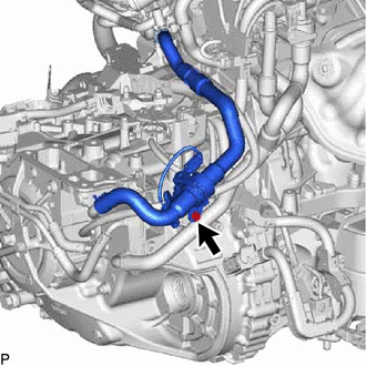
Remove the bolt and flow shutting valve (No. 1 water by-pass hose).