BRAKE CONTROL / DYNAMIC CONTROL SYSTEMS BRAKE PEDAL STROKE SENSOR(for RHD without Vacuum Brake Booster) REMOVAL
CAUTION / NOTICE / HINT
The necessary procedures (adjustment, calibration, initialization, or registration) that must be performed after parts are removed, installed, or replaced during brake pedal stroke sensor assembly removal/installation are shown below.
| Replaced Part or Performed Procedure | Necessary Procedure | Effect/Inoperative Function when Necessary Procedure not Performed | Link |
|---|---|---|---|
|
*1: When performing learning using the GTS. Click here( |
|||
| Auxiliary battery terminal is disconnected/reconnected | Perform steering sensor zero point calibration | Lane control system | ( ) |
| Parking support brake system (for HV model)* | |||
| Pre-collision system | |||
| Memorize steering angle neutral point | Parking assist monitor system | ()
|
|
| Panoramic view monitor system (for HV model) | ()
|
||
| Reset back door close position | Power back door system (for HV model) | ()
|
|
| Power back door initialization | Power door lock control system | ()
|
|
| Replacement of brake pedal stroke sensor assembly | ·
Clear the zero point calibration data and stored linear solenoid valve calibration data ·
Perform initialization and calibration of the linear solenoid valve ·
Perform yaw rate and acceleration sensor zero point calibration |
·
DTCs are stored ·
ABS warning light illuminates ·
Brake warning light / yellow (minor malfunction) illuminates ·
Slip indicator light illuminates ·
VSC disabled or malfunctions |
()
|
- NOTICE:
-
After the power switch is turned off, the radio receiver assembly records various types of memory and settings. As a result, after turning the power switch off, make sure to wait at least 85 seconds before disconnecting the cable from the negative (-) auxiliary battery terminal.
PROCEDURE

 1. PRECAUTION
- NOTICE:
-
After turning the ignition switch off, waiting time may be required before disconnecting the cable from the negative (-) battery terminal. Therefore, make sure to read the disconnecting the cable from the negative (-) battery terminal notice before proceeding with work.
58410B
2.REMOVE DECK BOARD ASSEMBLY
58416K
3.REMOVE REAR NO. 2 FLOOR BOARD
65351A
4.REMOVE BATTERY HOLE COVER
5.DISCONNECT CABLE FROM NEGATIVE AUXILIARY BATTERY TERMINAL
78110K
6.REMOVE ACCELERATOR PEDAL(W/SENSOR) ROD ASSEMBLY
89510D
7.REMOVE BRAKE PEDAL STROKE SENSOR ASSEMBLY
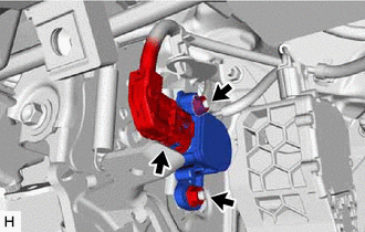
Disconnect the connector from the brake pedal stroke sensor assembly.
Remove the 2 nuts and brake pedal stroke sensor assembly from the brake pedal support assembly.
- NOTICE:
- ·
Do not drop the brake pedal stroke sensor assembly.
·If the brake pedal stroke sensor assembly has been dropped, replace the brake pedal stroke sensor assembly with a new one.