BRAKE SYSTEM (OTHER) BRAKE BOOSTER(for RHD with Vacuum Brake Booster) REMOVAL
CAUTION / NOTICE / HINT
The necessary procedures (adjustment, calibration, initialization or registration) that must be performed after parts are removed and installed, or replaced during brake booster assembly removal/installation are shown below.
| Replaced Part or Performed Procedure | Necessary Procedure | Effect/Inoperative Function when Necessary Procedure not Performed | Link |
|---|---|---|---|
|
*: When performing learning using the GTS. Click here( |
|||
| Battery terminal is disconnected/reconnected | Drive the vehicle until stop and start control is permitted (approximately 5 to 60 minutes) | Stop and start system | for A25A-FKS:
(  ) for M20A-FKS: ( )
|
| Perform steering sensor zero point calibration | Lane control system | ()
|
|
| Parking support brake system (for HV model)* | |||
| Pre-collision system | |||
| Memorize steering angle neutral point | Parking assist monitor system | ()
|
|
| Panoramic view monitor system (for Gasoline model) | ()
|
||
| Reset back door close position | Power back door system (for Gasoline model) | ()
|
|
| Power back door initialization | Power door lock control system | ()
|
|
- NOTICE:
- ·
After the ignition switch is turned off, the navigation system requires approximately a minute to record various types of memory and settings. As a result, after turning the ignition switch off, wait a minute or more before disconnecting the cable from the negative (-) auxiliary battery terminal.
·Make sure to release vacuum from the brake booster assembly before removing the brake master cylinder sub-assembly from the brake booster assembly.
PROCEDURE

 1. PRECAUTION
- NOTICE:
-
After turning the ignition switch off, waiting time may be required before disconnecting the cable from the negative (-) battery terminal. Therefore, make sure to read the disconnecting the cable from the negative (-) battery terminal notices before proceeding with work.
2.RECOVER REFRIGERANT FROM REFRIGERATION SYSTEM
for HFC-134a (R134a):
Click hereVehicle Interior>HEATING / AIR CONDITIONING>REFRIGERANT (for HFC-134a(R134a))>REPLACEMENT
for HFO-1234yf (R1234yf):
Click hereVehicle Interior>HEATING / AIR CONDITIONING>REFRIGERANT (for HFO-1234yf(R1234yf))>REPLACEMENT
3.DRAIN ENGINE COOLANT
for A25A-FKS:
for M20A-FKS:
47201
4.REMOVE BRAKE MASTER CYLINDER SUB-ASSEMBLY
73900
5.REMOVE LOWER NO. 1 INSTRUMENT PANEL AIRBAG ASSEMBLY
87211A
6.REMOVE NO. 2 AIR DUCT
84340
7.REMOVE STOP LIGHT SWITCH ASSEMBLY
47101A
8.REMOVE BRAKE PEDAL RETURN SPRING
9.SEPARATE WIRE HARNESS
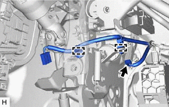
Disconnect the connector.
Disengage the 2 clamps to separate the wire harness from the brake pedal support assembly.
10.LOOSEN LOCK NUT
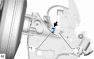
| *1 | Lock Nut |
| *2 | Brake Master Cylinder Push Rod Clevis |
Loosen the lock nut of the brake master cylinder push rod clevis.
47264A
11.REMOVE PUSH ROD PIN
44772
12.DISCONNECT CHECK VALVE TO CONNECTOR TUBE HOSE
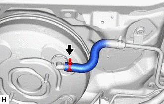
Slide the clip and disconnect the check valve to connector tube hose from the brake booster assembly.
44763A
13.DISCONNECT NO. 1 HOSE TO HOSE TUBE
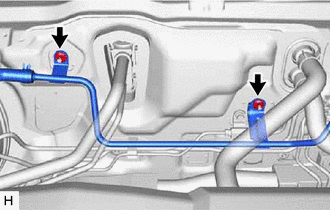
Remove the 2 nuts to disconnect the No. 1 hose to hose tube from the vehicle body.
88707
14.DISCONNECT SUCTION PIPE SUB-ASSEMBLY (w/o Sub-cool Accelerator)
for A25A-FKS:
Click hereVehicle Interior>HEATING / AIR CONDITIONING>AIR CONDITIONING UNIT (for A25A-FKS)>REMOVAL
for M20A-FKS:
Click hereVehicle Interior>HEATING / AIR CONDITIONING>AIR CONDITIONING UNIT (for M20A-FKS)>REMOVAL
88710E
15.DISCONNECT AIR CONDITIONING TUBE AND ACCESSORY ASSEMBLY (w/o Sub-cool Accelerator)
for A25A-FKS:
Click hereVehicle Interior>HEATING / AIR CONDITIONING>AIR CONDITIONING UNIT (for A25A-FKS)>REMOVAL
for M20A-FKS:
Click hereVehicle Interior>HEATING / AIR CONDITIONING>AIR CONDITIONING UNIT (for M20A-FKS)>REMOVAL
88710G
16.DISCONNECT NO. 2 AIR CONDITIONING TUBE AND ACCESSORY ASSEMBLY (w/ Sub-cool Accelerator)
for A25A-FKS:
Click hereVehicle Interior>HEATING / AIR CONDITIONING>AIR CONDITIONING UNIT (for A25A-FKS)>REMOVAL
for M20A-FKS:
Click hereVehicle Interior>HEATING / AIR CONDITIONING>AIR CONDITIONING UNIT (for M20A-FKS)>REMOVAL
47313
17.DISCONNECT FRONT NO. 3 BRAKE TUBE
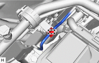
Disengage the clamp to disconnect the front No. 3 brake tube from the brake tube clamp.
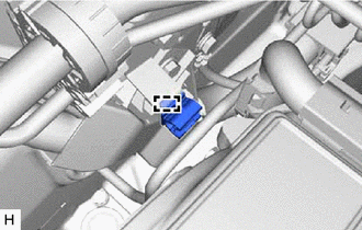
Disengage the clamp and remove the brake tube clamp.
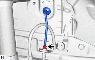
Using a union nut wrench, disconnect the front No. 3 brake tube from the front brake flexible hose.
- NOTICE:
- ·
Do not damage or deform the brake lines.
·Do not allow any foreign matter such as dirt or dust to enter the brake lines from the connecting parts.
88707
18.SEPARATE SUCTION PIPE SUB-ASSEMBLY
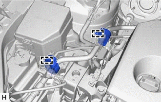
Disengage the 2 clamps to separate the suction pipe sub-assembly from the vehicle body.
44610
19.REMOVE BRAKE BOOSTER ASSEMBLY
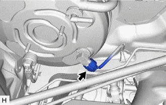
Disconnect the connector from the vacuum warning switch assembly.
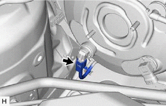
w/ Stop and Start System:
Disconnect the connector from the vacuum sensor assembly.
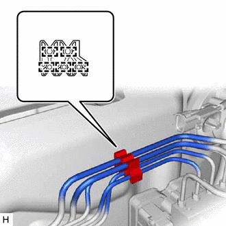
Disengage the 5 clamps to remove the brake tube clamp from the brake lines.
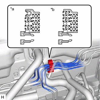
| *a | except Manual Transaxle |
| *b | for Manual Transaxle |
Remove the brake tube clamp.
for Manual Transaxle:
Disengage the 6 clamps to remove the brake tube clamp from the brake lines.
except Manual Transaxle:
Disengage the 5 clamps to remove the brake tube clamp from the brake lines.
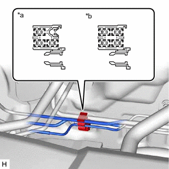
| *a | except Manual Transaxle |
| *b | for Manual Transaxle |
Disconnect the brake lines.
for Manual Transaxle:
Disengage the 4 clamps to remove the brake tube clamp from the brake lines.
except Manual Transaxle:
Disengage the 3 clamps to remove the brake tube clamp from the brake lines.
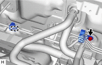
Remove the bolt and brake tube clamp from the vehicle body.
Disengage the clamp to remove the brake tube clamp from the vehicle body.
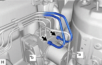
| *a | From 1st Chamber of Brake Master Cylinder Sub-assembly |
| *b | From 2nd Chamber of Brake Master Cylinder Sub-assembly |
Using a union nut wrench, remove the 2 brake lines from the brake actuator assembly.
- NOTICE:
- ·
Do not kink or damage the brake lines.
·Do not allow any foreign matter such as dirt or dust to enter the brake lines from the connecting parts.
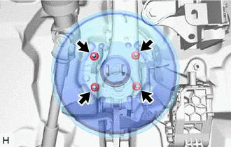
Remove the 4 nuts.
Remove the brake master cylinder push rod clevis and lock nut from the brake booster assembly.
Remove the brake booster assembly from the vehicle body.
- NOTICE:
- ·
Do not apply excessive force to the brake lines or refrigerant lines.
·Do not apply excessive force to the suction pipe sub-assembly.
44785
20.REMOVE BRAKE BOOSTER GASKET
Remove the brake booster gasket from the brake booster assembly.