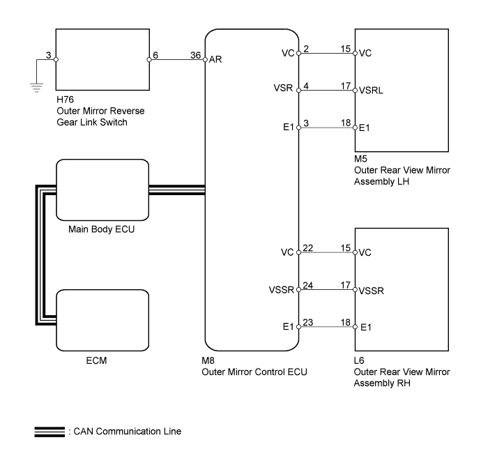
POWER MIRROR CONTROL SYSTEM (w/ Memory) > Reverse Shift-linked Function of Power Mirrors does not Operate |
| 1.CHECK DTC |
Use the Techstream to check if the CAN communication system is functioning normally (Click here).
| Result | Proceed to |
| CAN DTC is not output | A |
| CAN DTC is output | B |
|
| ||||
| A | |
 |
| 2.READ VALUE USING TECHSTREAM (PARK/NEUTRAL POSITION SWITCH) |
Connect the Techstream to the DLC3.
Turn the ignition switch to ON.
Turn the Techstream ON.
Enter the following menus: Powertrain / ECT / Data List.
According to the display on the Techstream, read the Data List.
| Tester Display | Measurement Item/Display | Normal Condition | Diagnostic Note |
| Shift SW Status (R Range) | PNP switch status / ON or OFF | ON: Shift lever in R OFF: Shift lever not in R | - |
| Result | Proceed to |
| OK | A |
| NG (A750E automatic transmission) | B |
| NG (A750F automatic transmission) | C |
| NG (AB60E automatic transmission) | D |
| NG (AB60F automatic transmission) | E |
|
| ||||
|
| ||||
|
| ||||
|
| ||||
| A | |
|
| 3.READ VALUE USING TECHSTREAM (MIRROR POSITION SENSOR) |
Connect the Techstream to the DLC3.
Turn the ignition switch to ON.
Turn the Techstream ON.
Enter the following menus: Body Electrical / Mirror / Data List.
According to the display on the Techstream, read the Data List.
| Tester Display | Measurement Item/Display | Normal Condition | Diagnostic Note |
| RH Mir Position Sensor V | RH side mirror vertical sensor voltage / MIN: 0 V, MAX: 5 V | Within range from 0 to 5 V | - |
| LH Mir Position Sensor V | LH side mirror vertical sensor voltage / MIN: 0 V, MAX: 5 V | Within range from 0 to 5 V | - |
| Result | Proceed to |
| Neither mirror operates normally | A |
| LH side mirror does not operate normally | B |
| RH side mirror does not operate normally | C |
| Mirror operates normally | D |
|
| ||||
|
| ||||
|
| ||||
| A | |
|
| 4.INSPECT OUTER MIRROR REVERSE GEAR LINK SWITCH |
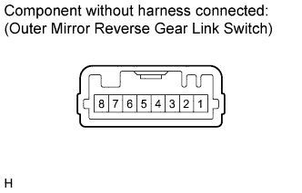 |
Remove the switch.
Measure the resistance according to the value(s) in the table below.
| Tester Connection | Switch Condition | Specified Condition |
| 3 - 6 | Pressed | Below 1 Ω |
| Not pressed | 10 kΩ or higher |
|
| ||||
| OK | |
|
| 5.CHECK HARNESS AND CONNECTOR (OUTER MIRROR SWITCH - OUTER MIRROR CONTROL ECU) |
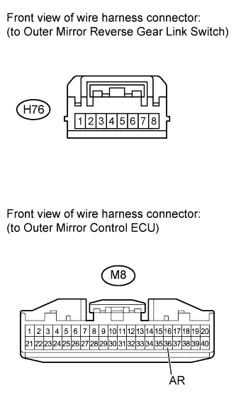 |
Disconnect the M8 ECU connector.
Disconnect the H76 switch connector.
Measure the resistance according to the value(s) in the table below.
| Tester Connection | Condition | Specified Condition |
| H76-3 - Body ground | Always | Below 1 Ω |
| M8-36 (AR) - H76-6 | Always | Below 1 Ω |
| M8-36 (AR) - Body ground | Always | 10 kΩ or higher |
|
| ||||
| OK | ||
 | ||
| ||
| 6.CHECK OUTER MIRROR CONTROL ECU |
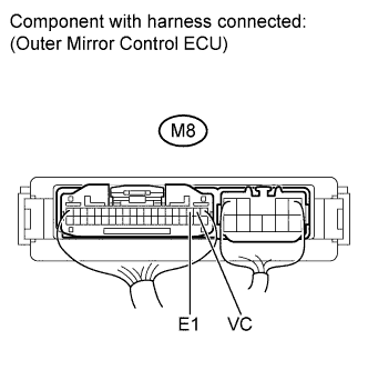 |
Measure the voltage according to the value(s) in the table below.
| Tester Connection | Switch Condition | Specified Condition |
| M8-2 (VC) - M8-3 (E1) | Ignition switch ON | 3.5 to 5.5 V |
Measure the resistance according to the value(s) in the table below.
| Tester Connection | Condition | Specified Condition |
| M8-3 (E1) - Body ground | Always | Below 1 Ω |
|
| ||||
| OK | |
|
| 7.CHECK HARNESS AND CONNECTOR (OUTER REAR VIEW MIRROR LH - OUTER MIRROR CONTROL ECU) |
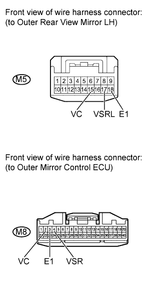 |
Disconnect the M8 ECU connector.
Disconnect the M5 mirror connector.
Measure the resistance according to the value(s) in the table below.
| Tester Connection | Condition | Specified Condition |
| M5-15 (VC) - M8-2 (VC) | Always | Below 1 Ω |
| M5-15 (VC) - Body ground | Always | 10 kΩ or higher |
| M5-17 (VSRL) - M8-4 (VSR) | Always | Below 1 Ω |
| M5-17 (VSRL) - Body ground | Always | 10 kΩ or higher |
| M5-18 (E1) - M8-3 (E1) | Always | Below 1 Ω |
| M5-18 (E1) - Body ground | Always | 10 kΩ or higher |
|
| ||||
| OK | ||
| ||
| ||
| 8.CHECK OUTER MIRROR CONTROL ECU |
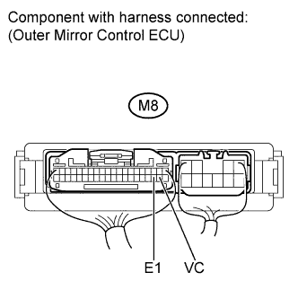 |
Measure the voltage according to the value(s) in the table below.
| Tester Connection | Switch Condition | Specified Condition |
| M8-22 (VC) - M8-23 (E1) | Ignition switch ON | 3.5 to 5.5 V |
Measure the resistance according to the value(s) in the table below.
| Tester Connection | Condition | Specified Condition |
| M8-23 (E1) - Body ground | Always | Below 1 Ω |
|
| ||||
| OK | |
|
| 9.CHECK HARNESS AND CONNECTOR (OUTER REAR VIEW MIRROR RH - OUTER MIRROR CONTROL ECU) |
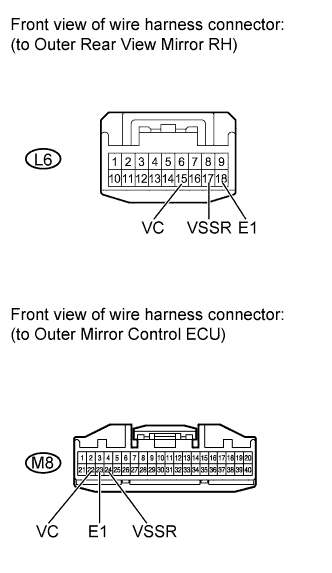 |
Disconnect the M8 ECU connector.
Disconnect the L6 mirror connector.
Measure the resistance according to the value(s) in the table below.
| Tester Connection | Condition | Specified Condition |
| L6-15 (VC) - M8-22 (VC) | Always | Below 1 Ω |
| L6-15 (VC) - Body ground | Always | 10 kΩ or higher |
| L6-17 (VSSR) - M8-24 (VSSR) | Always | Below 1 Ω |
| L6-17 (VSSR) - Body ground | Always | 10 kΩ or higher |
| L6-18 (E1) - M8-23 (E1) | Always | Below 1 Ω |
| L6-18 (E1) - Body ground | Always | 10 kΩ or higher |
|
| ||||
| OK | ||
| ||
| ||

